
Designing with Tantalum and Niobium Oxide Capacitors for NextGen Automotive Control Circuits
There are several main differences between standard reliability consumer electronic tantalum capacitors and TRJ products which result in enhanced reliability (0.5%/1000 hours) and reduced leakage current (to 75% that of standard tantalum specs). The changes include:
- The use of well-tested tantalum powders to ensure the long-term stability of electrical performance.
- Formation ratio, which is ratio between voltage used for electrolytical creating dielectrics and rated voltage is more than 3.0. It results in thicker and high quality dielectrics.
- Conservative design rules are followed both in design and manufacturing. Very strict quality control limits are applied and additional testing is performed. 100% hard surge current screening, extended electrical testing and accelerated burn-in processes are used to achieve and verify the high robustness of the parts.

The TRJ series capacitors are available both in standard and low ESR (equivalent series resistance) options, which make them suitable for a wide range of automotive control circuits in applications such as engine control units, ABS systems, MDPS, electronic gearboxes, TPMS, etc.
Ultra low ESR high performance tantalum capacitors
New series TRM capacitors combine the robust and reliable technology of the TRJ series (0.5%/1000 hours) with a remarkable multi-anode construction which uses several capacitor cores in parallel combination; this pushes ESR levels down to only 18, 23 or 25mΩ, depending on device selected.
Such ESR levels enable TRM capacitors to be used in DC/DC converters in various automotive applications.
High temperature tantalum capacitors
Standard tantalum capacitors technologies typically have a temperature range of –55degC to +125degC. Modern automotive electronics placed near the heat sources such as engines, headlights, gearboxes or cooller circuits, must operate up to 150 or even 175degC. With an operating temperature range of –55 to +175degC, AVX’s THJ Series meets this requirement. The category voltage, which is the maximum working voltage when actual operating temperature is considered, is 50% of rated voltage at 175degC. THJ Series tantalum capacitors also offer enhanced reliability (failure rate 0.5%/1000 hours) and a higher category voltage at 125 degC (78% of rated voltage) than standard devices have (typically 66 % of Vr).
Robust Niobium Oxide capacitors
NOJ OxiCap capacitors use niobium oxide powder as the main material for the anode electrode. Niobium oxide has much higher ignition energy (200 times) and much lower burning rate than pure metal materials such as tantalum or niobium. This feature means that OxiCap capacitors will not burn up to the category voltage. A further benefit concerns overload. A typical failure mode is high resistance (typically 20 to 200kΩ) after overloading by voltage spike or high current surge, which can result in increased leakage current and reduced capacitance. However, an OxiCap capacitor will continue to provide full capacitance and functionality – albeit at the expense of increased power consumption.
The NOJ OxiCap Series has a very high reliability level (failure rate 0.5%/1000 hours); low ESR NOS devices have an even lower failure rate (0.2%/1000 hours) – even more reliable than tantalum capacitors. They are suitable for applications with rail voltages of up to 8V, such as in-cabin entertainment systems, seat position modules, airbag controls etc.
Low and ultra low ESR Niobium Oxide capacitors
NOS is a low ESR Oxicap series with an even lower failure rate (0.2%/1000 hours) than NOJ. NOS together with NOM ultra low ESR multi-anode capacitors are suitable for application voltages up to 5V and represent the most reliable conventional capacitors in today’s automotive market.

Application guidelines for tantalum and niobium oxide capacitors in automotive circuits
For correct tantalum and niobium oxide capacitor design-in we have to consider all important electrical and physical conditions of the circuit and device where it will be used. The first parameter usually requested is the capacitance, which may be calculated from power line smoothing ratio, maximal voltage drop, etc. The next most important parameter to enable a correct selection of capacitor is the DC application voltage.
We must mention the general rule of recommended voltage application derating – 50% for all tantalum capacitors and 20% for Oxicaps; this means that AVX recommends the use of tantalum capacitors up to half their rated voltage Vr and Oxicaps up 80% of Vr. This is important to follow as a protection measure against unexpected current surges and over-voltages, which are highly probable, especially in automotive circuits. However, the derating margin for tantalum capacitors can be reduced for primarily output circuits (well separated from car battery line), circuits with protection against over-voltage and circuits with slow power up modes (soft start circuits. The output sections of low power DC/DC converters would be an example, and in such cases derating of only 20% is acceptable.
The application temperature range tells us – obviously – what capacitor series to choose due to the maximum operating temperature. However, it should be noted that additional voltage temperature derating must be applied at temperatures above 85degC. The maximum DC voltage allowed for a capacitor dependent on actual temperature is known as the category voltage (rated voltage is just one catalogue value for room temperature 25degC) – see Figure 1.

Figure 1: Category voltage – temperature derating graphs
If normal operation temperature exceeds 85degC permanently, both application and temperature derating should be combined. For example, consider a tantalum capacitor working at up to 125degC in circuit which is expected to see surges and voltage spikes. Application derating is 50%, (max voltage is 50% of Vr); temperature derating at 125degC (worst case) is 33% (max voltage can be 66% of Vr). Combining gives 0.5 x 0.66 = 0.33; meaning, for permanent usage at 125degC, the capacitor can be used at a maximum of 33% of rated voltage Vr.
The maximum application surge current (single peak) through the capacitor is important to know in order to avoid overloading the capacitor on power up or start up. Overload current can be calculated using the internal voltage of power source and internal resistances of all devices in series with the capacitor in question, including its ESR. The maximum surge current should lower than the capacitor’s maximum allowed surge current Ipmax = (1.1xVr)/ (0.45+ESR). If the application current is too high, additional derating can be applied, so a higher Vr capacitor must be chosen.
The capacitor’s maximum ripple current is dependent on the maximum AC current flowing through the capacitor. It has two main parameters – its effective value (rms, ACIrms, Ir) and frequency (f). Ripple current is limited by the maximum power dissipation (Pd) of the capacitor: (heat is generated by the current flowing through a capacitor when the ESR has non-zero value). The bigger the case size, the higher the allowed power dissipation; it is a constant value for each case size. A lower ESR results in less power to dissipate and therefore higher ripple current can be allowed – according to:
Pd = ESR x Ir x Ir
If the application calls for a high ripple current and low ESR, and the case size is not an issue, multi-anode construction is the best choice
From designer’s viewpoint the operating frequency mainly affects two parameters, capacitance and ESR, as in the example from AVX’s SpitanIII v1.1 software (see Figures 2 and 3).
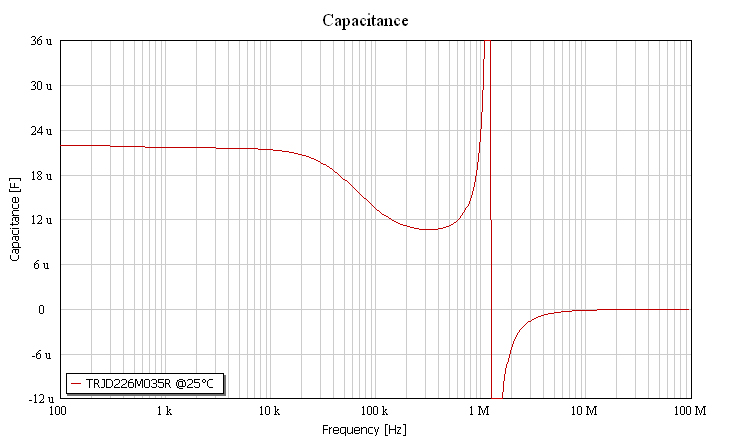
Figure 2: Example of Capacitance vs. Frequency characteristic

Figure 3: Example of ESR vs. Frequency characteristic
Figure 2 shows that capacitance decreases at higher frequencies; Figure 3 shows increasing ESR at lower frequencies. Both dependencies should be considered to assure sufficient capacitance and low enough ESR for the required ripple current.
The combination of application guidelines listed above will result in the correct capacitor selection. Alternatively the case size might be prioritized – for miniature or low profile applications, and the selection process adjusted accordingly. Sometimes, one capacitor alone is not sufficient, so two or more parts may be necessary – in this case, AVX basically recommends that only the same capacitor types are used in combination. Parallel connection increases capacitance (multiply) and decreases ESR (divide); serial connection increases total allowed DC voltage (rated voltage multiply), but decreases capacitance (divide) and increases ESR (multiply). For serial connection it is recommended that capacitors are connected in parallel with a resistor divider (where resistance of the divider resistors is calculated using a figure of 10 times the DC leakage current of the capacitors (catalogue value)).
About the author:
Ing. Radovan Faltus is Field Application Engineer at AVX Tantalum Division.
Faltus graduated to a master degree in Electronics and Microelectronics by the Czech Technical University of Prague in 2002. He has working experience in designing of electronics for one purpose machines and product marketing. He joint AVX Czech Republic s.r.o. in 2007 as a field application engineer responsible for technical support on tantalum capacitors. He can be reached via email: Radovan.Faltus@eur.avx.com
 If you enjoyed this article, you will like the following ones: don't miss them by subscribing to :