
How to Manage power in capacitive touch sensing applications
Capacitive touch sensing is replacing mechanical switches and push buttons in a wide variety of applications. Many battery-powered, handheld, and portable electronics have adopted capacitive touch sensing user interfaces. The power constraints of these devices, along with the constant focus on energy efficiency, has made low-power design critical in capacitive touch sensing applications.
Some best practices for reducing power consumption in capacitive touch sensing applications include:
. Optimize the sensor parasitic capacitance (CP) with board layout best practices
. Use sleep mode and optimize the sensor report rate
. Vary the report rate based on finger touch events
. Use the priority rule to wake up from sleep mode
Optimize the sensor parasitic capacitance (CP) with board layout best practices
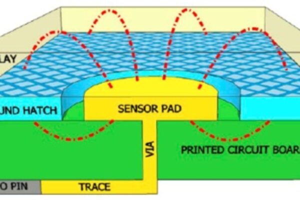
Capacitive touch sensors typically consist of copper pads connected to a capacitive sensing controller input pins via traces. Figure 1 shows a typical capacitive sensor including electric field coupling lines.

When a finger comes in contact with the overlay covering a sensor pad, it forms a simple parallel plate capacitor called finger capacitance (CF). Even without a finger touching the overlay, the capacitive sensing controller measures some parasitic capacitance (CP). CP is the sum of the distributed capacitance on the sensor. This includes the capacitance of the sensor pad due to its proximity to circuit ground, the trace connecting the capacitive sensing controller input pin and the sensor pad, vias, and the capacitive sensing controller input pin.
The capacitive sensing controller converts the capacitance measured at its input pin to digital counts using an A-to-D converter. The controller uses a DSP algorithm to continuously monitor the digital counts and identify increases in sensor capacitance due to a finger touch.
The main components of CP are trace capacitance and sensor capacitance. CP is a nonlinear function of the annular gap between the sensor pad and ground, the distance between the trace and ground, trace length and width, and the sensor pad diameter. There is no simple relationship between CP and PCB layout features but, in general, increasing the annular gap and decreasing the trace length and width will reduce CP. Unfortunately, widening the gap between the sensor pad and ground will decrease noise immunity. To achieve optimal CP and noise immunity, follow the capacitive sensing controller manufacturer’s PCB layout best practices.
Use sleep mode and optimize the sensor report rate
Report rate and sleep mode work together to define how the capacitive touch sensors are sampled, as shown in Figure 2. Report rate defines how often the sensors are sampled by the A-to-D converter. When a sensor is sampled, the capacitive sensing controller is in active mode. When a sensor is not being sampled, the controller can be put into sleep mode. In sleep mode, the controller powers down all internal blocks and peripherals. This mode is supported by most of the capacitive sensing controllers on the market.

Selecting a low report rate and a longer sleep time are the keys to reducing the average power consumption. Report rate and sleep mode directly affect the capacitive sensing controller’s average current consumption, as defined in Equation 1.

IActive = Current consumed by the controller when it is sampling a sensor
TActive = Time it takes the controller to sample all of the sensors
ISleep = Current consumed by the controller when it is in sleep mode
TSleep = Amount of time the controller remains in sleep mode
As a general rule of thumb, a human finger cannot touch a button faster than 150 ms. Typical A-to-D conversion times range from 200—6000 µs. This means that several A-to-D conversions can be performed during the 150 ms a sensor is being touched. Optimize the report rate for your specific A-to-D conversion time.
Reducing CP helps to reduce TActive because the controller can use a lower A-to-D converter resolution. Selecting a capacitive sensing controller with lower active current reduces IActive. Keep in mind that sleep mode current has a minimal impact on the average current.
Vary the report rate based on finger touch events
When selecting the report rate, consider how a user will interact with your device. Consumer electronics may be powered on for hours at a time without a finger touching the user interface. For example, the buttons on an audio system or a TV remote are only used once in a while, when something like the volume or channel needs to be changed. However, once a button has been touched, the user might touch multiple buttons to get the intended result.
Based on this example, sensors can be sampled less frequently (low report rate mode) until a button touch is detected, at which time the report rate can be increased (fast report rate mode) to enable quick response to subsequent touches, as shown in Figure 3. If a finger touch is not detected for certain period of time, the capacitive sensing controller can revert back to low report rate mode. Using a programmable capacitive sensing controller allows you to dynamically change the report rate based on touch events.

Figure 3: Low vs. fast report rate modes
Click on image to enlarge
Use the priority rule to wake up from sleep mode
In some applications all buttons should not be able to wake the capacitive sensing controller from sleep mode.
For example, when a TV is turned off, the controller only needs to detect a finger touch on the power button to turn the TV on. In this application, when the power is off the controller only samples the power button and does not sample any of the other buttons on the TV’s front panel. This reduces TActive, and significantly reduces average power consumption.
Let’s take a look at typical TV front panel:
. Eight capacitive touch sensing buttons
. Sampling time = 500 µs per button
. IActive = 4 mA
. TActive = 10 ms
. ISleep = 1 µA
. TSleep = 90 ms
Using Equation-1, when all buttons are sampled:
IAverage = 160 µA
When only the power button is sampled:
IAverage = 20 µA
In the second part of this article, I will discuss other methods of optimizing average power in capacitive touch sensing designs such as:
– Using a ganged capacitive sensor method to wake up from sleep mode
– Using a proximity sensor to wake up from sleep mode
– Using an external regulator to turn off power
– Using the low power option specific to the capacitive sensing controller
About the author
Vibheesh B is a Senior Applications Engineer working in Cypress Semiconductor’s Consumer and Computation Division and has specialized on Capacitive Touch Sensing applications since 2007. His responsibilities include defining technical requirements for new capacitive sensing controllers, developing new capacitive sensing controllers, conducting system analysis, debugging technical issues for customers, technical writing, and failure-analysis debugging.
Related posts
. Digital power techniques threaten analog power-supply obsolescence
. Teardown: The power inverter – from sunlight to power grid
. Power device consideration for optimized design of LED power supply
. Power-line modems, power supplies, and "cleaning up the neighborhood"
. Optimizing FPGAs for power: A full-frontal attack
. ‘Early and accurate’ power analysis: myth or reality?
. Maximizing savings at cell sites through deployment of hybrid energy solutions
 If you enjoyed this article, you will like the following ones: don't miss them by subscribing to :