How to structure a battery management system
So you’ve been tasked to design the monitor circuitry for a new battery-based power system. What strategies will you employ to optimize the design for cost and manufacturability? The initial considerations will be to determine the preferred structure of the system and the location of the cells and electronics involved. When the basic structure is understood, then one must consider the tradeoffs in the circuit topology such as, how to optimize communications and interconnection within the final product.
The form factor of the cells being considered will have a significant influence on the structure of the power system. Will there be a large number of small cells to fashion complex-shaped modules (or pack), or will large format units be used that impose weight limitations on cell count or other dimensional constraints? This is perhaps the biggest area of design flux, as new cell formats enter the market and efforts are made to more organically integrate the module or pack structures into an overall product concept. In the case of vehicle design, for example, batteries may well end up being distributed over the vehicle in otherwise inefficiently utilized spaces.
Another consideration is the interconnection of test signals and/or telemetry between the cells (or their modularized groupings), BMS (or sub-sections thereof), and final application interface. In most situations, a case can be made for integrating some of the data acquisition circuitry within the module or pack so that if interchanged, important information like production ID, calibrations, usage metrics, etc. can travel with the replaceable elements. This information can be useful for the BMS or service equipment, and it minimizes the number of high-voltage-rated wires required in the harness.

Figure 1. Different Battery Monitoring Topologies. For full resolution, click here.
The topology of the monitoring hardware is then driven by the refined definition of the cell-count to be supported for a given mechanical concept. In a vehicular application, it is typical to see upwards of 100 total cell measurement points, and the modularization of the system will dictate how many cells are to be measured by a given electrical assembly. Most commonly, the overall cell count is subdivided into at least two electrical subsections by way of a safety disconnect “service plug.” This minimizes the possible electrical hazard for service personnel, by keeping the voltage to below 200V in a fault scenario. Larger pack formats implies two sets of isolated data acquisition systems, supporting perhaps 50 cell taps apiece. In some cases, all the electronics are on one economical printed circuit assembly but this requires a large number of interconnects as depicted in Figure 1(a). Alternatively, the electronics may be distributed and more intimately integrated in modules, but this requires a telemetry linking method. For reliable data integrity, telemetry incorporated into vehicle harnessing must use a robust protocol, such as the ubiquitous CAN-bus. While a true CAN-bus interface involves several network layers, the PHY layer can be readily adopted to form a BMS LAN structure for efficient inter-module communication. Such a distributed structure is shown in Figure 1(b). This topology allows the computational workload to be distributed amongst several small processors, thereby reducing the required data transmission rates and potential EMI issues with the LAN approach. The eventual BMS application interface is likely to be a CAN-bus connection to a main system management processor, and the specific information transactions will need to be defined (or specified at the outset).
Additional factors can also have implications on the physical structure and monitoring circuitry. Cell-balancing is required for Lithium-Ion cells, creating extra thermal-management issues (heat removal) and/or power conversion circuitry if active balancing is required. Temperature probes are usually distributed throughout a module to provide means of correlating voltage readings to state-of-charge, and thus require some support circuitry and connection schemes. One often overlooked design consideration is that the batteries should experience the lowest possible battery drain during times when the product is idle or stored on shelves prior to installation. In some cases, extra control wiring becomes necessary.
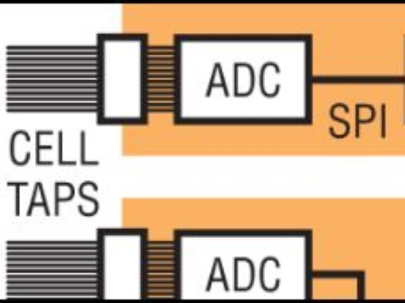
In any of these structural implementations, there is a common measurement functional block that includes a multichannel ADC, safety isolation barrier and some level of local processing capacity. The circuit of Figure 2 shows a scalable design platform for the data acquisition function. In this diagram, the heart of the function is a Linear Technology LTC6803 battery stack monitor IC, shown along with an SPI data isolator and some optional special purpose circuitry. This circuit includes input filters and passive balancing facilities that form a complete 12-cell data acquisition solution. Such circuits can simply be replicated as needed to support larger cell measurement scenarios, while sharing the local SPI port of a host microcontroller that in turn provides for the external CAN-bus or other LAN-style data link.
A major improvement over previous generation monitoring devices is that the LTC6803 supports having power shutdown and/or power furnished separately from the cell stack. When power is removed from the V+ pin, cell loading will drop to zero (nano-amp level semiconductor leakage only). Operational power can be from a switched cell stack potential or furnished to V+ from a separate source as long as the voltage is always at least as large as the cell stack. For simplicity, the LTC6803 can also take power directly from the cell stack, in which case the lowest power state (i.e. standby) will consume just 12uA. The LTM2883 data isolator is powered from the host processor with an internal isolated DC-DC converter, so it will automatically power down along with the host. A very useful feature of the LTM2883 is that it can also furnish significant host-derived power to the isolated electronics (i.e. battery side). A small boost supply function (the LT3495-1 in Figure 2) is driven this way to independently power the LTC6803 so that the battery cells will only provide the current of the ADC measuring inputs (i.e. <200nA average during active conversions). This circuit offers the absolute lowest parasitic battery drain possible and simultaneously eliminates any operational cell current mismatches that might otherwise promote gradual cell imbalances.
A handy feature of the LTC6803 is that there are two uncommitted ADC inputs with similar accuracy of the cell inputs. This convenient facility allows auxiliary measurements to be taken with little additional circuitry, including temperatures, calibration signals, or load current. One particularly useful metric is the voltage of the full battery stack with a gated resistor divider as shown implemented within Figure 2 (uses 12:1 scaling, connected to the VTEMP1 input). The associated FET is turned off when the circuit powers down, so the measuring current does not needlessly burden the cells. Since filtering of this port can be tailored independently from the cell inputs, true Nyquist sampling rates of up to 200sps are possible for precision charge-flow calculations.
The individual cell measurements can be used to periodically provide a software calibration of the full-stack divider so the resistors do not need to be an expensive type. Another very useful application of an auxiliary input is to measure a high-accuracy calibration source (such as the Linear Technology LT6655-3.3, a 0.025% accuracy reference), which allows software to correct all the other channels by virtue of intrinsic channel-to-channel matching. Note that thermistor temperature probes need not be referenced to cell potential, and they don’t generally require 12-bit resolution. Such probes are usually suitable for connection directly to a microcontroller, thereby leaving the high performance LTC6803 auxiliary inputs for the more demanding functions.

Figure 2. Complete 12-Cell Isolated BMS Measurement Function
In conclusion, many factors need to be considered in a battery management system circuit, particularly those that dictate packaging constraints. When the packaging concept is coming together, it is also important to consider the structure of the electronics and the information flow that can also have mechanical ramifications, such as connectorization and wire count. Once these factors are weighed and the concept matures, just drop-in a proven, scalable and cost effective data acquisition solution using an LTC6803 platform.
About the author: Jon Munson is Senior Applications Engineer, Linear Technology.
 If you enjoyed this article, you will like the following ones: don't miss them by subscribing to :