Monitoring, modelling and analysis of batteries for electromobility
Electrochemical impedance spectroscopy (EIS) is becoming increasingly important as a technique for dimensioning and characterizing batteries and other electrochemical systems. The advantages of this non-invasive measurement method can be exploited not only in modelling energy storage units such as batteries and fuel cells, but also in the fields of basic battery research and diagnostics. In many cases it is now possible to dispense with highly complex laboratory assemblies and measurement systems in favour of monolithic System-on-Chip solutions integrated into the battery system itself.
What was the motivation for this application?
The main point at issue is to ensure a permanent source of electric power whilst at the same time main functions are increasingly being realized by means of electronic equipment. Effective registration of the true state of a battery cell – in respect of performance, state of charge (SOC) and ageing (state of health, SOH) – as well as aspects such as cell monitoring, performance forecasting, operating strategy, thermal management, cell balancing, cell ageing and high-voltage charge management are decisive factors which determine how far a vehicle can travel per charge and how long the battery will last altogether.
However, these physical and/or electrochemical variables can only be defined in a usable way if the battery can be subjected to an exact mathematical definition as well as modelled and represented in the form of a complex equivalent circuit. EIS provides a valuable contribution towards achieving this end.
At present, lithium-ion batteries represent the most promising storage technology option available for use in the coming generation of hybrid vehicles. However, irrespective of the technology involved, the communication between cells and/or stacks represents one of the elementary necessities within the total system. In order to address this aspect, HAW Hamburg has developed system proposals (Fig. 1) for connecting cell sensor elements and cell balancing elements to the control device.
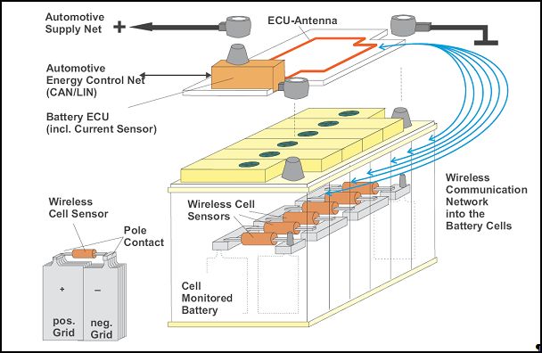
Fig. 1. Possible system integration in vehicle (Source: HAW Hamburg , Faculty of Technology and Informatics, Department of Information and Electrotechnology
From a start/stop system via hybrid drive to the purely electric car
Types of electrically driven vehicles range from those with simple start/stop systems via mild-hybrids with torque enhancement of the combustion engine using an electric motor to the full-hybrids. Parallel full-hybrids are driven directly either by a combustion engine or by an electric motor. In serial full-hybrids, on the other hand, the drive is purely electric. Here, however, a so-called range extender (in the form of a small internal combustion engine) can be activated if necessary in order to recharge the batteries. The greatest challenge within the present range of battery technologies is presented by the purely electrically driven vehicles.
Battery management: Much more than the measurement of current and voltage
Energy storage technology is a key technology on the path towards the development of alternative, environmentally friendly drives. In order to achieve a high packing density and at the same time optimal thermal management and low weight, so-called flat prismatic cells are implemented. These cells have an advantage over conventional round cells in that their high surface to volume ratio allows for very efficient cooling.
Such cooling is also very necessary. To prevent accelerated ageing of the Li-ion cells, the operating temperatures in the cell core must be kept within the limits defined by the manufacturer. Typically, these range from 40°C to 60°C.
According to the Arrhenius equation, the ageing process depends on the temperature in batteries such that a rise in temperature of 10K causes the ageing rate to double. In order to ensure that the required temperatures are maintained at all operating times, it is necessary to cool the battery. This means that the battery and thermal management systems must be designed with the aid of electrical and thermal simulations and models. By monitoring each individual cell (state of charge; state of health) and also through intelligent combination of the data gained with the battery’s thermal management system as well as the implementation of appropriate control algorithms in the battery management system (BMS) it is possible to prevent early ageing of the battery cells.
Implementation of electrochemical impedance spectroscopy (EIS)
Electrochemical impedance spectroscopy has now reached a stage in which it can be used not just under laboratory conditions, but also in mass-produced articles. Amongst others, this includes applications in industry and in the area of electrical mobility. Examples of such applications include impedance based ageing monitoring (state of health, SOH) and use in online battery monitoring in vehicles.
For in addition to its suitability for evaluating battery current and voltage, impedance spectroscopy can also be used to monitor the internal resistance of the batteries. Impedance monitoring has proved to be especially useful as a means of gauging the ageing process for batteries used to supply an uninterrupted power supply (UPS). Figures 2 and 3 show the results of a large scale ageing experiment with continuous monitoring of the battery impedance. Regular measurements of the remaining capacity and internal impedance of various battery blocks and individual cells were conducted during an artificial ageing test at a higher temperature.

Fig. 2. Increase in battery impedance of a UPS lead battery during artificial ageing at 65°C ambient temperature
Figure 2 shows the amount of the impedance over the frequency for each ageing stage. The age data is obtained from the artificial ageing. The batteries were stored at 65°C at a constant voltage. This is approximately equivalent to an ageing factor of 16 compared with room temperature. Figure 3 shows the measurement results for a complete battery bank, in each case with the development of the battery impedance of the individual blocks and their corresponding measured capacity. The figure indicates that there is a relationship between the impedance gradient and the capacity loss. However, it has so far not been possible to establish any direct and generally valid correlation between the impedance and the capacity. Nevertheless, the continuous monitoring of the battery impedance does allow for rapid registration of differences between individual blocks, especially in the case of large battery banks.

Fig. 3. Development of the impedance and the capacitance of a battery bank during an artificial ageing process. The curves show the development of individual battery blocks of the bank.
On-board battery diagnosis in the vehicle
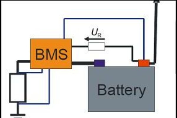
The growing number of electronic control devices in vehicles increases the demands made on the on-board network battery. For this reason, on-board diagnosis for the dedicated starter battery in the vehicle is becoming more and more important. Generally, a battery sensor is connected to a battery management system (BMS) and consists of a resistance (shunt) or Hall sensors for current measurement, a voltage sensor and a temperature sensor.
All of these parameters are evaluated by the BMS in order to obtain information about the state of the battery. Here, too, impedance spectroscopy can be of assistance by supplementing the current and voltage measurements with frequency-dependent impedance data. There are two ways of doing this: so-called active excitation using signal generators mounted on the chip or passive excitation. The passive excitation method is based on the exploitation of disturbances caused by active electronic loading of the on-board network (as shown in Fig. 4). Current flow and voltages are analysed for a filtered frequency range with the help of basic mathematical functions. This enables the impedance of the battery to be calculated.

Fig. 4. Use of passive impedance spectroscopy for the on-board diagnosis of starter batteries.
Basic principles of impedance spectroscopy with active excitation
Electrochemical impedance spectroscopy is performed on batteries by submitting the test piece to sinusoidal alternating current and measuring the voltage response. In addition, direct current can be overlaid in order to set the working point of the test piece. With the help of discrete Fourier transformations it is then possible to calculate the complex impedance of the test piece in accordance with the equation:

The measurement method for impedance spectroscopy using the MD8710 from Infineon (described in a later section) is shown in principle in Fig. 5. In this case Z1, Z2 and Z3 are mixed complex networks and represent the battery’s equivalent circuit. In order to enable excitation of the battery with higher currents a power stage must be inserted between the MD8710 and the battery.

Fig. 5. Schematic representation of connections in a 4 point measurement The current measurement signal is routed internally in this configuration. The return routing of the current measurement signal can also be done via the second A/D converter channel.
By varying the excitation frequency it is possible to determine a complete impedance spectrum Z(f). Fig. 6 shows the spectrum of a Li-ion cell for various charging currents. It can be seen that there is a clear interrelationship between the voltage response and the overlaid direct current – especially for lower frequencies. The figure also shows the frequency range under investigation. For impedance measurements on batteries, this is typically from several kHz to very low frequencies of a few mHz or even some tens of μHz.

Fig. 6. Impedance spectrum of an Li-ion cell with overlaid charging currents of differing strengths in a Nyquist display
The Nyquist visualization shows the negative imaginary part displayed above the real part. This type of representation makes it easier to interpret electrical equivalent circuits, and with a little practice it is possible to evaluate changes in an individual element quite quickly when the spectrum changes.
Cell monitoring and diagnosis require a networked system
One of several prerequisites for an ‘intelligent’ energy management system suitable for all battery technologies consists in the transmission of remotely collected battery data to a local collection point of a central BMS where it can be stored (see Fig. 1). From this location the data can then be passed on to an online service provider if required, where all data can be gathered and evaluated. By this means it is also possible to compare and correlate statistical data from entire vehicle fleets. In turn, the fleet database can serve as a data source for deriving control parameters.
To meet just this requirement, Rutronik has now developed an exclusive, highly integrated chip solution in partnership with Infineon: the Single Chip Analytical Device MD8710. This device contains an ARM-Cortex-R4 processor as core unit, a comprehensive Memory Protection Unit, an Interrupt Controller, a DMA Controller and a Watchdog Timer.
The analogue front end of the component can cope with applications which place high demands on the analogue signal processing. It is equipped with two independent16 bit ADCs and two 16 bit DACs. The DAC channels can be fed with data from an integrated wave table generator, whereas for the analogue pre-processing two freely configurable, high-ohmic OPAs per ADC are available (for instance as transimpedance amplifiers for current inputs). For the purposes of additional system integration, the MD8710 has a 12 bit ADC with four external auxiliary multiplex inputs and a temperature sensor.
Two completely separate DAC channels for signal synthesis and two ADC channels for signal analysis operate fully simultaneously and synchronously. This allows for the determination of current, voltage and phase. Data exchange can be realized both via a USB 2.0 interface as well as via a Bluetooth module integrated in the chip. As well as this, the following interfaces are present: I2C, SPI and UART.
Using an external voltage source, the Power Management Unit (PMU) generates and monitors all the required voltages for the chip’s own supply. The PMU can manage various energy saving and wake-up scenarios and is also responsible for the charge control of a Li-ion or LiPo battery, e.g. for remote Low-Power-Point-of-Load supply to the central control device – without a connection to the main battery being analysed.
Furthermore, the MD8710 is equipped with a display controller which supports matrix LDCs and provides additional audio functions, e.g. for issuing warning sounds or for speech output. Equally, the four integrated PWM outputs can be used for direct control of semiconductor performance switches for the purposes of cell balancing.
Cost savings through high level integration and platform concept
A starter kit for the evaluation of the new component will be available shortly. With this kit it will be possible to redefine battery management systems, together with external performance switches for active cell balancing, and then implement them in practical situations.
The next major task must now be taken on by the battery manufacturers and automotive OEMs: the modelling and simulation of cells, stacks and/or complete batteries.
About the authors:
Andreas Mangler: In September 2007, Andreas Mangler took over the post of Director of Strategic Marketing at Rutronik Elektronische Bauelemente GmbH. Mangler has been with the company for 17 years and before taking on this post he was already Line Management Manager. His email address is andreas_mangler@rutronik.com.
Martin Kiel is scientific staff member in the Electrochemical Energy Conversion and Storage Technology research group. This group belongs to the Institute for Power Conversion Technology and Electrical Drives (ISEA), which in turn is affiliated to the RWTH Aachen.He can be contacted via batteries@isea.rwth-aachen.de
Sources of information:
[1] Kiel, M; Sauer, D.W.: Impedanzspektroskopie an Batterien – D&E Entwicklerforum.
[2] Gronwald, F.: Intelligente Batteriesensorik. Auto Kabel Management GmbH
[3] Schöllmann, Dr. M.: Intelligente Batteriesensorik (5.6.2004); www.hanser-automotive.de/fileadmin/heftarchiv/2004/3278.pdf
[4] Data sheet MD8710 Product Overview Revision 0.5, 2011-03-28.
[5] Forster, F.: Intelligentes Batteriemanagement; So lasten Sie Akkus in Hybrid- und Elektrofahrzeugen optimal und sicher aus. Elektronik Praxis (15.03.2010)
[6] MST-Projektinformation BMBF, VDE, VDI, IT; Entwicklung einer Lithium-Ionen-Batterie für automotive Anwendungen – LiHeBe (26.5.2010); Project partners: Behr, RWTH Aachen, Li-Tec Battery – Project promotion number: 16SV3680.
 If you enjoyed this article, you will like the following ones: don't miss them by subscribing to :