Protecting vehicle battery systems from transients, shorts, and other faults
The high-voltage battery array and its connection to various subsystems such as the drive train and other high-power electrical systems requires isolation so the battery system “floats”, thus preventing leakage currents or high voltages from reaching low-voltage systems and the vehicle chassis. The onboard charger of plug-in electric vehicles takes in high voltage line voltage (240 V) and draws high currents for overnight charging. The need for high-voltage protection against transients is extremely critical. Car manufacturers are looking to standardize battery management systems to handle battery arrays that deliver up to 1000 V.
To deliver the necessary levels of isolation, optical isolators are the defacto standard way to provide high electrical isolation and high noise immunity while consuming little power compared with systems that use transformer coupling to provide the isolation. Battery subsystems are especially challenging due the large number of cells typically used, the high levels of electrical noise, and substantial transients that occur from the loads presented by the vehicle to the charging currents that recharge the cells. Additionally, in the design of the battery array itself and the charging subsystem, monitoring each cell’s voltage within the array is a key concern such that a cell failure will not cause the entire array to stop functioning or cause the charging system to overload.
A typical battery array in an electric vehicle consists of multiple battery modules, with each module typically consisting of many individual cells and specialized circuits that monitor the cells in the module. The total array typically delivers an output of several hundred volts (typically about 400 V). The monitoring circuits capture the battery voltage and other parameters and digitize the collected data and send the data over a serial peripheral interface (SPI) bus to the microcontroller (MCU) that manages the battery subsystem (Figure 1). The MCU, in turn sends control signals over the control-area-network (CAN) bus to various subsystems in the vehicle.
To isolate the battery subsystem from the MCU, optical isolators take the serial data from the SPI output of the cell monitoring circuits and provide a physical barrier thanks to the separation of the LED emitter and the light-sensing receiver. Isolation levels of several thousand volts prevent transients, electrical noise, or other factors from breaching the system. This allows the battery system to “float” with no direct connection to the body of the vehicle. Additionally, current leakage is also minimized since there is no connection to the vehicle body.
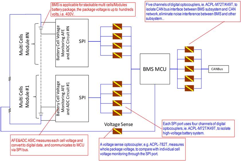
Figure 1: A typical battery management subsystem requires multiple optocouplers to provide isolation between the SPI bus and the microcontroller, and between the microcontroller and the CAN bus. For full resolution click here.
In the battery subsystem different types of optocouplers provide different levels of voltage isolation and performance to match the performance needs of each portion of the system (Figure 2). For instance, the SPI interface would typically operate at data rates of over 1 MHz and would have to deliver its performance over a -40 °C to +125 °C operating temperature range. Those requirements would lead to the use of optocouplers such as the ACPL-K49T or a similar optocoupler from other vendors to isolate the low-speed chip-select signal, and higher-speed optocouplers such as the ACPL-M72T or equivalent for the three higher-speed SPI signal lines (serial clock, serial data in, and serial data out) from each battery monitoring circuit (Figure 3).

Figure 2: Four signals from the SPI port on the battery measurement circuit use optical isolators to ensure no high-voltage spikes cross from the battery array to the low voltage microcontroller.
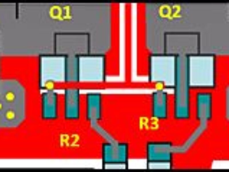
The ACPL-K49T is a single-channel optocoupler with a very simple architecture that consists of the LED emitter, the isolation barrier, a photodiode receiver and a transistor amplifier (Figure 3, left). The device handles data rates of up to about 20 kbits/s, offers a high common-mode rejection – 30 kV/µs at a VCM of 1500 V, and a low LED drive current (4 mA, minimum). In contrast, the ACPL-M72T has a more-complex receive-side architecture that couples the photodiode to a transimpedance amplifier and a voltage comparator with an output driver to better handle driving the SPI bus (Figure 3, middle). The optocoupler can operate at data rates of up to 10 Mbits/s and has a propagation delay of 100 ns, maximum, yet it also consumes just 4 mA of drive current.
Handling the isolation on the voltage sense line to protect the MCU from transients or noise, an analog optocoupler such as the ACPL-782T will sense the analog voltage of the battery array, and send the result to the BMS system MCU (Figure 3, right). The MCU, in turn, will compare it to the sum of all the cell’s voltage and diagnose if the system is operating properly and if not, can send warning messages to the rest of the systems in the vehicle to alert the operator that something is wrong. Additionally, the MCU could also send control feedback to the charging circuits for the battery array, adjusting the charge parameters or shutting the charging subsystem done if a major fault was detected.
In a typical implementation, the battery voltage distributed across a string of series resistors is sensed at one tap by the ACPL-782T as shown in Figure 1. A differential output voltage is created on the other side of the ACPL-782T’s optical isolation barrier. This differential output voltage is proportional to the motor current and can be converted to a single-ended signal. Since common-mode voltage swings of several hundred volts in tens of nanoseconds are common in modern switching inverter motor drives, the ACPL-782T was designed to ignore very high common-mode transient slew rates (of at least 10 kV/µs). The high CMR capability of the ACPL-782T isolation amplifier provides the precision and stability needed to accurately monitor motor current and DC rail voltage in high noise motor control environments, providing for smoother control (less “torque ripple”) in various types of motor control applications.

Figure 3: Two different optocouplers are used on the SPI interface. The ACPL-K49T (left) is a low-speed device that easily handles the chip-select signal, while the ACPL-M72T (middle) is a higher-speed optocoupler with a transimpedance amplifier and output driver to handle the higher signal speeds of the clock, serial data in, and serial data out lines. The right-side diagram of the ACPL-782T details the differential voltage and current sensing capability that makes the device a good fit for battery and motor monitoring applications. For full resolution click here.
Once data is sent to the BMS MCU, the MCU analyzes the data and then sends control signals via the CAN bus to the charge management system, the drive-train control, the dashboard, and other subsystems in the vehicle. Depending on the MCU selected, the CAN controller could be co-integrated on the same chip as the MCU, or it can be a separate chip. In most systems, the CAN controller is a separate IC, since that allows the isolation to be positioned between the MCU and the CAN controller rather than on the CAN-bus itself (Figure 4). In this scenario, the CAN bus can operate at maximum speed and not be constrained by the optical isolators.

Figure 4: Between the MCU and the CAN bus controller the five signal lines are optically isolated to prevent noise, transients, and high-voltage spikes from affecting signal integrity or damaging the low-voltage circuits.
The MCU is thus doubly isolated – on the inputs by the optocouplers on the SPI bus, and on the outputs by the optocouplers between the MCU’s I/O pins and the inputs to the CAN controller. In the subsystem shown in Figure 4 five optocouplers provide the isolation to the CAN controller. Three of the five devices are low-speed couplers such as the ACPL-K49T, which was also used on the Chip-Select line between the battery-management controller and the MCU. The two remaining optocouplers in the CAN subsystem are used for the transmit and receive data lines between the MCU and the CAN control chip. These optocouplers must handle a much higher data rate – typically about 500 kbits/s and thus the ACPL-M72T or a similar optocoupler would be an appropriate choice for the isolation.
About the author: Junhua He is Senior Technical Marketing Engineer for automotive isolator products at Avago Technologies and is based in Singapore. He started his career with the company as part of the Semiconductor Products Group of Agilent Technologies in 2000 and has held various positions in R&D, Applications and Marketing since then.
 If you enjoyed this article, you will like the following ones: don't miss them by subscribing to :