Putting cars in to motion
Control systems, of all types employ closed-loops that rely on feedback in a bid to assess cause and effect; once the effect has been assessed, the cause (or stimulus) can be modified, a reiterative process that improves the time to result exponentially. Not surprisingly this closed-loop approach to control enables many applications, but it is also now being applied extensively to improve the efficiency of a growing number of others.
A key element to this trend is the availability of reliable, responsive and robust sensors, which form a critical link in the feedback chain. Sensors, in general but particularly those that rely on a measurable, physical change in the sensor material (caused by exposure to the condition/property being measured) are commonplace, often passive and have well defined limitations. The introduction of micro electro-mechanical systems, or MEMS, however, is breaking down these barriers to how, where and for what sensors can now be used.
Probably the most widely reported, researched and developed application for MEMS sensors is the measurement of inertial change in the form of acceleration and orientation (accelerometers and gyroscopes, respectively). Their tiny dimensions and robust construction mean MEMS sensors can be used in harsh environments where space is limited, to create use-cases that would not be possible without them.
In automotive systems, MEMS sensors now enable a growing range of control solutions that deliver greater efficiency and safety in vehicles; MEMS now enable safety features such as airbags, antilock braking systems, electronic stability programs and electronically controlled suspension, as well as advanced driver-assist systems such as hill start assist and electric parking brake features, lane departure warning, automatic cruise control and more.
Broadly speaking, MEMS sensors in automotive are used to enable or enhance safety; typically, in passive safety systems, such as airbags, the sensor acts as a trigger. Conversely, active systems, such as antilock braking, active suspension or stability control, require more sensitivity and performance, being overall more demanding than an airbag which only requires a relatively simple ‘switch-like’ response.
Fundamentally, however, both employ accelerometers implemented in MEMS technology, typically sensing the movement of a suspended mass, detected in the form of a capacitive change. As well as measuring an increase/decrease in acceleration, accelerometers use the same principle to detect a range of effects, including tilt/inclination, shock/vibration and centrifugal force. Sensors, such as gyroscopes, are typically used to detect pitch, roll and yaw, while accelerometers detect linear movement in the X, Y and Z-axes.
The use of multiple sensors allows more sophisticated control, while many safety systems require just one sensor, often in a single plane. One such application is electronically controlled suspension systems, where the important axis of interest is essentially only the Z axis, given that a car’s movement, predominantly in the X/Y axes, can be improved under all road conditions by dynamically adjusting the suspension.
Unlike passive systems, active safety relies more heavily on degrees of change. This demands sensors that offer an output calibrated to represent a window of inertial change (effectively the gravitational mass), which in turn requires greater sensitivity when measuring the degrees of change in capacitance caused by the mass moving. The speed and accuracy with which any resolvable change can be detected therefore dictates the efficiency of the sensor in a given application.
Sensitivity is directly influenced by the manufacturing process used to create the micro-structures; most MEMS processes use either bulk or surface micro-machining to create structures. Bulk micro-machining techniques employ selective etching (normally KOH-wet etching) of a silicon wafers, which allow features to be created inside the structure by etching through the wafer; surface micro-machining, on the other hand, uses deposition (and etching) to build structures layer-by-layer on a substrate, or etching structures on top of the wafer.
Ostensibly, bulk micro-machining offers greater stability and scaleability, while surface micro-machining is more compatible with traditional IC fabrication, allowing simpler active circuit integration. However both also have their associated drawbacks and the difference between the two has, in recent times, become less distinct with the evolution of MEMS manufacturing technology.
This is evident in the proprietary 3D MEMS technology developed by Murata; a combination of bulk and surface micro-machining. This technology offers many benefits: formed from a single crystal the silicon is uniquely suited to being a MEMS substrate, with no plastic deformation up to 70,000g. It also allows direct capacitive sensing of deflection, without loss, giving a highly accurate and stable measurement. The ability to create ‘true’ 3D structures supports 3D sensing elements with low temperature dependence and zero point stability, while yielding the highest signal per silicon surface area. It also supports the design of flexible two-chip solutions, such as combining a sensor with an ASIC to create a solution with tuneable sensitivity and frequency response, for use in specific applications.
The sensitivity required is dependent on the given application; an electronic stability control system requires greater sensitivity and offset stability than an airbag system (for example, although as mentioned earlier these two applications would be classified as active and passive safety systems respectively).
As such it is necessary to design sensors with a specific sensitivity, which in this context equates to the correlative quantium.

Figure 1 shows how sensitivity is measured in terms of correlative quantium and quantium change.
For example if sensitivity is 2V/g, 1g acceleration results in a 2V change in the output. Typically, the requirement for MEMS sensors designed for electrically controlled suspension applications will be to have a full range analogue output of 0 to 5V, whereas the accelerometers for electronic stability control systems in use today use mainly digital outputs in the form of a SPI interface.
The combination of mechanical and electrical elements now enables a wider range of application-specific MEMS sensors, such as the single-axis accelerometer recently introduced by Murata (SCA720-D01), which joins its growing range of MEMS sensors targeting suspension and engine vibration applications in the automotive market. With a simple 3-wire connection and analogue output, the sensor is small and robust enough to be mounted directly on the suspension system, providing fast and accurate feedback to the electronically controlled suspension system’s ECU.
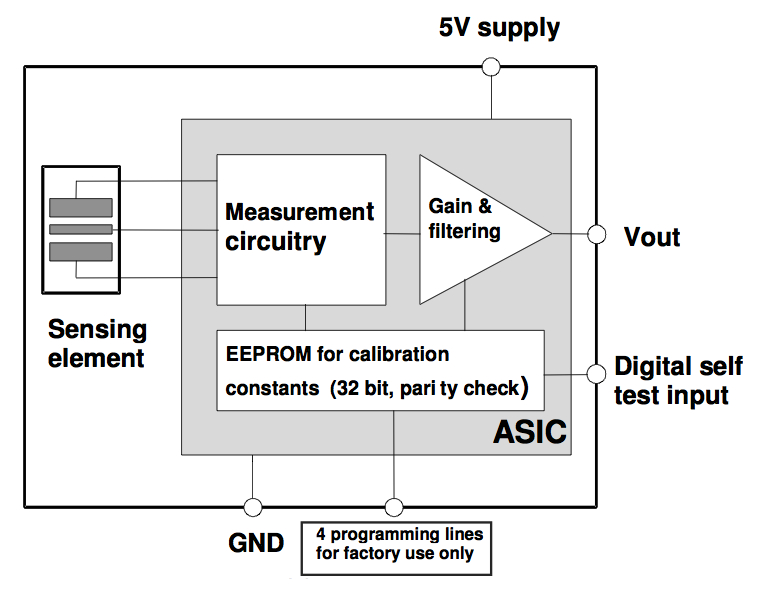
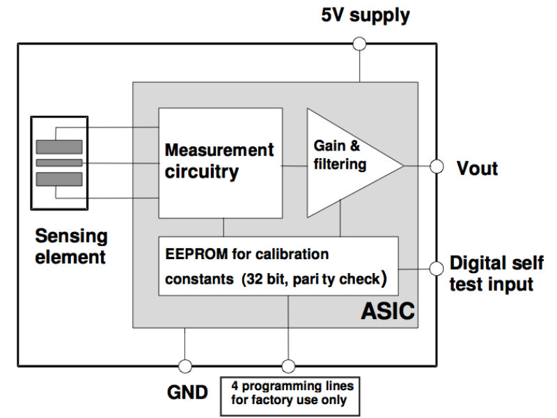
Figure 2 shows a block diagram of the SCA720-D01.
Manufactured using bulk micro-machining and housed with a signal conditioning ASIC, the SCA720-D01 achieves a nominal sensitivity of 0.9375 V/g. From this, acceleration can be calculated as a function of the output voltage and sensitivity, as shown in Equation 1. Note that the Vout(0g) is the nominal output voltage at 0g position, with a 5V supply. In order to maintain accuracy, the device also employs a ratiometric output feature, which ensures that the output voltage is less susceptible to supply voltage variations; a ratiometric output indicates that if the supply voltage fluctuates then the output voltage will fluctuate proportionally. Furthermore, when the same reference voltage is used for both the sensor and the A/D converter in the signal chain, any error caused by the reference voltage variation is automatically compensated for.
The SCA720 also includes a built-in self-test mode, which simulates acceleration (or deceleration) using an electrostatic force. This force simulates acceleration high enough to deflect the proof mass to the extreme positive position, causing the output voltage to reach its maximum value.
The operating environment including EMI/EMC for this type of sensor can be classed as harsh and as the amount of electronics used in cars increases so too due the (global) list of requirements to which they must adhere. The requirements of reliability are also much more stringent in the automotive field. It is now commonplace to test components to in excess of 2000 temperature cycles, where the requirement used to be less than 1000 cycles between -40 and +125 degree C. Manufacturing MEMS sensors to meet these increasingly stringent requirements demands a depth of knowledge only acquired through experience; Murata has been developing MEMS sensors for the automotive market for more than 20 years and uses that experience to continuously drive down the size and cost of MEMS sensors, while driving up stability, reliability and performance.
About the author:
Jari Nieminen is Product Manager at Murata Finland.
 If you enjoyed this article, you will like the following ones: don't miss them by subscribing to :