
Real fuel chemistry facilitates accurate clean engine design
Accurate, fast chemistry simulation is required for predictive to predict ignition calculations, predictive engine knock simulations and predictive emissions calculationsin engines. The RD software package robustly and accurately simulates engine-cylinder combustion performance for reciprocating engines, with virtually any fuel, helping engineers rapidly design clean, high-efficiency, fuel-flexible engines. Engine simulation applications include spark ignitiongasoline, diesel, and advanced designs such as Homogeneous Charge Compression Ignition (HCCI), PCI and PPCI [PCCI?], multiple fuel injections and dual-fuel engines.
The process by which fuel ignites and burnsof combustion can be modeled effectively using a detailed chemical mechanism of the fuel describing the thousands of short-lived species and chemical reactions that dictate how a fuel ignites, how the flame propagates, and how emissions like NOx, CO, and soot are formed. Accurately modeling real fuel behavior requires more chemistry than traditional Computational Fluid Dynamics (CFD) approaches can handle with acceptable time-to-solution. As most commercial CFD improvements directed toward better accuracy have focused on enhancing meshing and turbulence modeling, there has been little effort directed toward improving the fundamental chemistry calculations, to reflect the key engine behaviors that are now beginning to dominate the design space. Given that chemistry calculation times in CFD can account for 90% of the total simulation time even when employing severely reduced mechanisms, there is substantial opportunity for decreasing time-to-solution by accelerating these calculations.

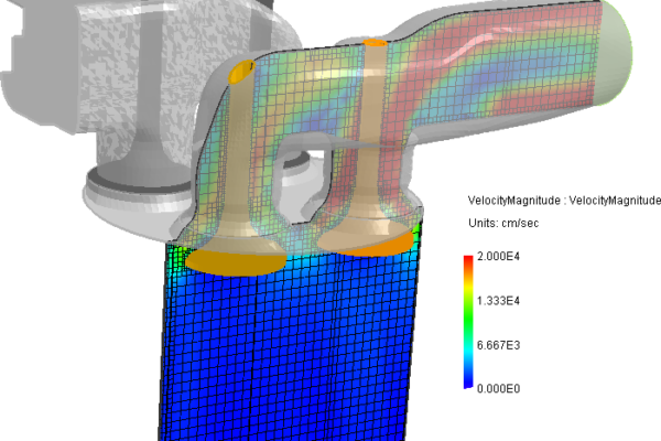
Visualization of the combustion process in a diesel engine
FORTÉ is a comprehensive CFD package that allows the engine designer to go directly from CAD drawings to simulation results in far less time than other CFD software, while taking advantage of real fuel chemistry models for better results without the need for expert calibration. Accurate modeling of realistic fuel effects is viable with superior time-to-solution metrics that fit in commercial-development timeframes. FORTÉ employs a novel solver approach that takes advantage of the chemical similarity of groups of cells and implements a parallel processing algorithm to dramatically reduce the chemistry calculation time. This technique can reduce simulation run times by almost two orders of magnitude. Chemistry models that previously were thought of as only practical for 0-D simulations are now practical for full 3-D engine simulations complete with moving pistons and valves.
The Model Fuels Consortium (MFC), an industry-led program, has developed the detailed chemical mechanisms needed to simulate real fuel behavior. Most chemistry models in use today are slow and lack sufficient detail for accurate and predictive results. While it is widely accepted that the use of more detailed chemical mechanisms is required for accurate prediction of important characteristics of the combustion process such as ignition, flame propagation and emissions production, many designers don’t believe they have the option of incorporating these mechanisms into their simulations without significant increases in compute time and solution instability. As a result, designers cannot rely on their combustion CFD to predict values or even accurate trends in these critical combustion behaviors.
Larger, more accurate fuel mechanisms can be incorporated into the simulation to achieve runtimes similar to those with much smaller, less accurate mechanisms. The FORTÉ CFD package employs innovative techniques to achieve these unprecedented calculation speeds: Dynamic Cell Clustering leverages an advanced algorithm to group those cells that have similar kinetic conditions at each time-step and eliminates duplicate calculations. Dynamic Adaptive Chemistry automatically reduces the kinetics on the fly at every time-step, to use only the chemistry required at that time. This method leads to huge savings in solution time with no loss in accuracy. When combined with RD’s proprietary chemistry-solver technology, these techniques generate highly accurate results in solution times that are several orders of magnitude faster than chemistry solvers used with other commercial CFD packages.
Advanced spray models dramatically reduce grid and time-step dependency
The choice of spray models can have a significant impact on both time-to-solution and the accuracy of results. Many spray models are highly mesh dependent, requiring that valuable time be spent refining the mesh, or adding mesh complexity, to find an acceptable combination of model parameters and grid mesh. Even when a spray model is calibrated to a particular grid, it is unclear how accurate the model will be when attempting to predict the behavior of a different engine design. FORTÉ’s multi-component spray model maintains consistency between the physical properties of the engine and the chemical model of the fuel to more accurately capture droplet evaporation and ignition. This allows for a more accurate spray model without the need to drastically increase mesh refinement. Less calibration means better portability to other designs.
The FORTÉ CFD Package includes an automated mesh generator that facilitates rapid analysis of variations in geometry, such as bowl shape, bore size, valve angles and more. Without advanced chemistry, automatic mesh generation is just a faster path to the wrong answer. The FORTÉ Automesher generates meshes on the fly without introducing numerical errors or increasing run times. Mesh movement is handled smoothly and robustly, while accounting accurately for piston and valve motion. Meshes can also be imported from common third-party tools such as ICEM-CFD or GAMBIT. KIVA-3V meshes are also easily imported.
The FORTÉ CFD Package includes a comprehensive visualizer that quickly generates graphical representations of simulation results in a form engine designers need. Visualizations are intuitive and interactive, with support for cut-planes, line probes, phi-T map generation and external data import, eliminating the need for 3rd-party post-processing tools.
No separate tools are needed to gather, collate and view results. This visualizer provides quick creation of animations for any 3-D view, 3-D contour plots with easy control of both the cut-planes and the viewing angles; import of experimental data, automatic unit conversions, and quick comparisons of parameter-study results; automated creation of Phi-T maps to show where and when emissions are produced, including animations and last but not least export to third-party tools, including Field view, Insight, Tecplot and Excel.
Automatic mesh generation eliminates weeks of effort
Automatically generating a mesh at runtime enables grid refinement and geometric parameter studies and improves Timetime-to-Solution solution by removing the meshing "bottleneck" in the design flow. With virtually no intervention from the user, FORTÉ reads CAD files directly and imports the detailed geometry information it needs to automatically generate a high-quality, well-structured, Cartesian mesh. The advanced automatic mesh-generation technology in FORTÉ includes full valve motion and 3-D mesh capability.
For a Cartesian mesh, the Local Truncation Error (LTE) is minimized, because the structure of the Cartesian mesh is regular. Of course, some non-uniformity in the mesh is introduced at solid-fluid interfaces. Typically, the mesh is refined at the boundary, such that the regular and uniform-sized cells are split into a number of smaller control volumes. In this way there is irregularity in the form of "hanging nodes" that must be dealt with in cells adjacent to a change in refinement level (or density) in the mesh. The proportion of these cells reduces as a smaller base mesh is used. The cells in a refined layer, however, are also regular or cubic in shape, unless a cut-cell approach is used. Overall, irregularity is minimized the closer the mesh is to being fully Cartesian
The automatic mesh generation technique utilized in FORTÉ is based on a unique immersed-boundary theory. It allows the use of a Cartesian mesh that is faster to create, more robust and less prone to error than other approaches, such as body-fitted unstructured or pure cut-cell meshes. The automatic mesh generation works from the inside-out, requiring only that you specify one point within the domain that is always "inside". In addition, just a few user-defined mesh-size controls are required to make sure that the mesh refinement around exceptional features (valves, etc.) is accomplished adequately
The automatic mesh generation begins by importing the engine geometry, typically from a CAD program in the form of an STL file. Then any splitting or merging of surfaces needed to separate specific engine components, e.g., head, valves, and piston, is performed within the FORTÉ Simulation Interface. The mesh generated during the simulation is based on a global maximum cell size specified in the setup. Optionally the mesh may be refined around important features, such as valve seats, or dynamically at critical times during the simulation, such as near firing top-dead center (TDC). The mesh is automatically created at every time step during the simulation.
Conventional CFD gridding meshing techniques require that valuable time be spent refining the mesh, or adding mesh complexity, to find an acceptable combination of spray model parameters and grid mesh. From an accuracy point of view, however, the ideal mesh is one that is Cartesian, with perfectly orthogonal faces, and one in which the boundary conditions can be applied exactly on the physical surfaces of the real geometry. Both unstructured-mesh and cut-cell approaches require a very large degree of mesh refinement at the boundaries to approximate the real boundary surfaces for useful geometries (such as a cylinder). This translates to longer compute times, especially when chemistry calculations are needed in each cell.
The mesh generation process begins with the definition of the rectangular computational domain. Three sets of planes orthogonal to the Cartesian coordinate system are then defined inside it. The intersection of these planes defines the set of rectangular cells (cuboids) that form the background Cartesian mesh. At the next stage of the process, specified refinement levels are honored for areas near specific boundaries or geometric elements, such as spark plugs or valve seats, or for volumetric regions defined by spheres or “tubes” of interest. These refinement levels can be specified initially or can be imposed at some specified time windows during the simulation. The refinement is imposed, such that difference in refinement levels of neighbor cells is never higher than 1; this is necessary to minimize the approximation error. The refinement level of the cell is the number of times it has been refined relative to the initial cell in the background Cartesian mesh.
When a cell is refined, it will be evenly split into eight smaller cubes. Engine geometries inevitably contain small structures, such as the crevice between valve seats and the cylinder head. Such small fluid passages have to be resolved using very small cells, and it is impractical to use such small cells throughout the computational domain. This makes mesh refinement a necessary capability. In FORTÉ, mesh refinement can be applied on boundary surfaces or in specified volumetric regions.
FORTÉ does not rely on "adaptive" cell refinement to maintain accuracy of the combustion solution. Especially for combustion, where sudden large gradients in the solution occur, adaptive refinement can be highly error-prone, since the solution will shift as the refinement is initiated. Instead, FORTÉ relies on careful use of mesh-independent models to resolve flame-propagation and spray structures. However, it is important to note that these features relieve the mesh-generation process from constantly needing large numbers of small cells in regions that are not known a priori in a simulation. Instead, FORTÉ can rely on simple refinement around known fixed boundaries, or low-level global refinement for time periods of known interest.
Built-in visualization capability saves time and effort
The FORTÉ CFD Package includes a comprehensive visualizer that quickly generates graphical representations of simulation results in a form engine designers need.
No separate tools are needed to gather, collate and view results. This visualizer provides quick creation of animations for any 3-D view, 3-D contour plots with easy control of both the cut-planes and the viewing angles; import of experimental data, automatic unit conversions, and quick comparisons of parameter-study results; automated creation of Phi-T maps to show where and when emissions are produced, including animations and last but not least export to third-party tools, including Field view, Insight, Tecplot and Excel.

Forté user interface and 3D visualization example
Recently new capabilities were added to FORTÉ: the ability to accurately simulate soot particle size as well as total particulate-matter emissions. The new technology was inspired by the accomplishments of the Model Fuels Consortium (MFC). Founded in 2005 by Reaction Design, the award-winning MFC is a highly regarded, industry-led project for the development of cleaner burning, higher-mileage vehicles. More than 20 members include Volkswagen, Peugeot (PSA) as well as US and Japanese automotive OEMs. The MFC’s work focuses on creating software models and tools that enable engine designers to better determine the fuel effects on efficiency and emissions. When coupled with an accurate soot chemistry mechanism, such as the one developed by the MFC, the FORTÉ soot model provides engine designers with a physics-based approach to the prediction of soot size and mass emissions trends with unprecedented accuracy.
Soot formation occurs when fuels don’t fully combust. While in the past decade, engine exhaust regulations focused on limiting the total amount of soot, and NOx emissions, future regulations will include particulate matter as well. The Euro 5+ and Euro 6 standards and proposed U.S. Tier 3+ and Tier 4 regulations limit both mass and number of particles. Various medical studies have shown that soot is unhealthy, especially particulate sizes of less than 2.5 microns – the human body cannot eliminate such small particles. Designing an engine that minimizes the amount of soot produced is much more cost-effective than aftertreatment
The MFC contracted with the University of Southern California to obtain needed fundamental measurements that were used to validate the soot model parameters. The model accurately predicts engine-out trends, including total mass emissions and particle size distribution. This allows engine designers to compare disparate engine designs or combustion schemes relative to one another. The MFC and Reaction Design have been working proactively to develop soot modeling approaches that can help reduce these harmful emissions, as we anticipate that more regulations will follow with increasingly strict limits on particle size and number. The ability to predict soot particle sizes and track their progress from formation through agglomeration and oxidation in an engine is of significant benefit for engine developers, who will not only be able to better address air quality regulations, but also help shave time from their design cycle.
About the author: Bernie Rosenthal is CEO of Reaction Design
 If you enjoyed this article, you will like the following ones: don't miss them by subscribing to :