

Accurate 3D Measurement of Magnetic Fields for Automotive Gear Selector
Conventional linear Hall sensors, Hall switches and angle sensors are only able to recognize magnetic field components that are perpendicular to the surface of the chip; Giant Magneto-Resistive (GMR) angle sensors measure only the planar-oriented field components. However, the TLE493D-W1B6 sensor is capable of simultaneously determining the x, y, and z coordinates of the magnetic field (Figure 1). Recognition of the magnetic field components of all three axes provides a holistic, three dimensional image of the magnetic field in which the sensor lies. Any movement of the magnet leads to a change in at least one of the magnetic field components, which is recognized by the 3D sensor.

all three field directions of a magnetic field (x, y, and z)
The three dimensional sensor system is made possible by the integration of both vertical and horizontal Hall plates into a single sensor chip. The vertical Hall plates detect the planar-oriented x and y field components, while the horizontal Hall plate detects the vertically oriented field component (z direction).
Several innovative, patented concepts were applied in the development of the sensor. Users can define a magnetic field corridor for each magnetic field direction such that if the measured magnetic field lies outside of the corridor, the sensor sends an alert signal to the connected microcontroller. A further development goal was the reduction of power consumption. Thanks to innovative design technologies, such as the energy-saving oscillator, the sensor’s power consumption was reduced to only a few nanoamperes – 7 nA when in “power down” mode, for instance. The result is a silicon component that fits into a small package despite its large functional scope. The TSOP-6 case with six pins is only 2.9 x 1.6 mm in size – making it smaller than any other 3D magnetic sensor on the market.
Because of its low power consumption and its integrated magnetic field alert, the TLE493D-W1B6 is suitable for use in applications that must detect regular changes in position while using very little power. In addition, it allows the realization of precise, energy-saving system concepts that can be activated by a sensor alert. The sensor’s magnetic field alert, for example, can be used to wake up the microcontroller from its power-saving “sleep” mode. This alert is triggered whenever a change of the magnet’s position alters the magnetic field.
The sensor is equipped with a digital output that uses a two-wire I²C standard interface. This allows high communication speed and bus mode.
Qualified in accordance with the AEC-Q100 automotive standard, the device allows customer systems to comply with the highest quality standards and various environmental regulations. In addition, all relevant ISO 26262 documents are provided in order to fulfill functional safety system requirements.
Architecture and Primary Features
The sensor architecture consists of three primary function units (Figure 2) – power mode control unit, sensor unit and communication unit.

The power mode control unit serves to distribute energy in the integrated circuit (IC) as well as controlling sensor activation.
The sensor unit, which contains the vertical and horizontal Hall plates and a temperature sensor, measures the magnetic field in the x, y, and z directions. Use of vertical Hall plates for both planar magnetic field components (x and y direction) allows the sensor to achieve outstanding magnetic reconciliation accuracy (±1 %), enabling precise angle measurements. Each x, y, and z Hall plate is connected in series to a multiplexer which is connected to an analog-to-digital converter (ADC). The temperature sensor is also connected to the multiplexer and can be activated if desired.
The microcontroller always has access to the communication unit through an I2C interface and to the register data in order to read out the register values. Values for the three axes and the temperature are stored in separate registers. While the interface fulfills the I2C fast-mode specification (400 kBit/s), an optimized electrical circuit allows data rates above 1 MBit/s to be supported. The sensor can also be used in an I2C bus scheme with other devices in accordance with the I2C protocol guidelines.
During 3D magnetic field detection, the TLE493D-W1B6 offers 12-bit data resolution for every measurement direction. This enables high data resolution of 0.098 mT/bit (least significant bit, LSB), which allows even the smallest movement of the magnet to be measured. Linear measurements of the magnetic field (B) in relation to each of its axes (Bx, By, and Bz) are also possible for the large linear field range (±150 mT). This means an even longer linear magnetic movement (up to 4 cm) can be measured. The large measurement range also enables a simple, robust, flexible magnetic circuit layout.
Flexible Power Modes for Lowest Power Consumption
After each measurement cycle, the sensor transmits a strong interrupt signal to the connected microcontroller, which can then read out the magnetic and temperature values from the registers. The sensor’s interrupt signal can be used to wake up the microcontroller system from its sleep mode. If the entire system is in sleep mode and only activated in the read-out phase, the total power consumption of the system as a whole is reduced dramatically.
The TLE493D-W1B6 can operate in different modes. Individual operating modes vary by their numbers of measurement cycles per second (Figure 3) and the sensor can be set to the desired mode flexibly during operation.

operating modes that can be selected
In power down mode, all functional blocks are shut down. In this mode, no magnetic measurements are performed and power consumption drops to 7nA.
In “fast” mode, the readout speed is optimized. While the measurement result is read out, the next magnetic field measurement can be performed. This mode is particularly suited to applications for which very fast magnetic movements must be detected. The sensor’s power consumption is, at most, 3.7 mA at a sampling rate of about 8 kHz, corresponding to 8,000 measurement cycles/second.
A total of eight different “low power” modes have been implemented in the TLE493D-W1B6. In all of these modes, the sensor regularly and autonomously wakes up out of power down mode in order to perform magnetic measurements. The power consumption depends on the number of measurement cycles/second (see Figure 3).
In “master-controlled” mode, the sensor can be flexibly read out according to the requirements of the application. After each measurement, the sensor waits until the microcontroller (master) has read out the register. Depending on the application conditions, the read-out process can be performed immediately or with a slight delay. As soon as the microcontroller has detected the magnetic values, a new sensor measurement cycle is triggered. This mode is particularly useful when several TLE493D-W1B6 sensors are connected through an I²C bus for the detection of large linear movements. The microcontroller decides which sensor’s data is most relevant and triggers the corresponding sensor.
Application: Gear Selector in a Mid-Range Car
A magnetic 3D sensor is very useful in detecting the position of the gear selector in an automobile as the existing ‘state-of-the-art’ solution, which uses at least six Hall switches, can be replaced by a single 3D sensor. Because the TLE493D-W1B6 has the same case dimensions as modern Hall switches, a great deal of space, as well as money, can be saved.
Using a gear selector for a current mid-range car as an example, here we will evaluate how the 3D sensor provides an alternative to the current solution.
Figure 4 (left) shows six gear selector positions on a circular arc at intervals of about 6 °. The original gear selector is detected by means of a Hall switch in each of the six selector positions. These six Hall switches can be replaced by a single TLE493D-W1B6 3D sensor (Figure 4 right).
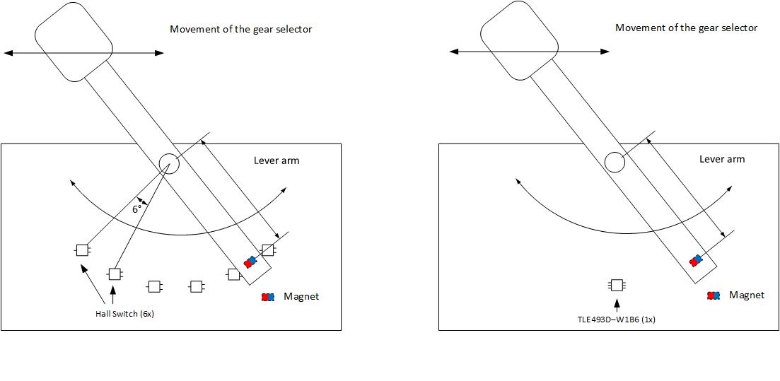
with six Hall switches (left) and a single 3D
magnetic sensor (right)
For a robust magnetic design, the following parameters should be used:
- Magnet shape: Cuboid shaped (7 x 5 x 3 mm)
- Magnet material: NdFeB
- Remanence: 1 T
- Sensor: TLE493D-W1B6
- Air gap between sensor and magnet: 4 mm
- Magnetization: Axial
- Lever arm: 1.3 cm
- Swept angle: 0 … 30 °
- Six positions result in a resolution of 6 ° per position
The parameters above allow linear behavior between the mechanically deflected angle and the calculated spherical angle Theta (Ɵ). The spherical angle is calculated from the sensor’s x, y, and z components (Figure 5).

with a 3D magnetic sensor
This allows the angle to be determined unambiguously, which in turn enables an unambiguous determination of the selector position. A detailed description (application note) is available at www.infineon.com/3dmagnetic.
Functional Safety
The TLE493D-W1B6 is also equipped with test functions that make possible malfunction detection during operation, allowing the complete sensor signal chain to be assessed at any time. The test delivers a defined value that the microcontroller can compare with the expected value. If the expected value is obtained, the master does not need to initiate further measures. Test times are significantly lower than 1 ms.
Alert Function
A further intelligent feature of the TLE493D-W1B6 is the magnetic field alert. For all three magnetic field directions, a corridor can be determined in milliTeslas for magnetic field strength. The magnetic field is cyclically measured in the set mode and compared with this corridor. If the measured magnetic field value remains within the corridor in all three directions, the sensor suppresses the interrupt signal. If the measured magnetic field value exceeds the upper corridor value or falls below the lower one, the sensor initiates an interrupt and wakes up the microcontroller (Figure 6). When the master (microcontroller) becomes active, it reads out the magnetic field values from the registers. The corridor can be set for all three axes at any time and independently of each other. This allows the thresholds to be adjusted in reaction to changes in mechanical positions.

for the magnetic field alert function
Using the magnetic field alert means that the entire microcontroller system can be set to sleep mode, with the sensor only waking the microcontroller and the connected systems when the magnetic position indication changes. This enables the development of systems that save a great deal of energy, but are nevertheless capable of reacting quickly to a change in position.
Summary
The TLE493D-W1B6 sensor provides precise and energy-efficient 3D magnetic field detection for various applications. Flexible operating modes offer dedicated and scalable system designs with a wide measurement range for precise position determination and very low power consumption. The integrated magnetic field alert can wake up the microcontroller systems in order to inform them of a change in position.
Development samples of the TLE493D-W1B6 are available. Volume production is planned for the end of 2016.
About the authors
Hannes Birk studied electrical engineering at the Constance University of Applied Sciences, Germany and earned an MBA from the TiasNimbas Business School, Netherlands. He is responsible for 3D magnetic sensors and linear Hall sensors at the Automotive Division of Infineon Technologies in Neubiberg, near Munich, Germany. Email: hannes.birk@infineon.com; Phone: +49 89 234 26320
Sigmund Zaruba studied physical engineering in Munich, Germany. He has been with Infineon Technologies for 15 years as an application engineer and is currently responsible for 3D magnetic sensors and Hall switches at the Automotive Division of Infineon Technologies, Neubiberg near Munich, Germany. Email: sigmund.zaruba@infineon.com; Phone: +49 89 234 26648
 If you enjoyed this article, you will like the following ones: don't miss them by subscribing to :