Monitoring & Switching Power in Automobiles
It’s easy to appreciate the benefits of the electronics that power the many functions in a modern vehicle, from our heated seats, air conditioning, navigation, infotainment and safety systems designed to increase comfort and our overall driving experience. It’s hard to imagine what it must have been like just over 100 years ago when there was not a single electrical component in gasoline-powered automobiles. Turn of the century automobiles were started with hand cranks, headlights were lit with acetylene gas and pedestrians were alerted with a ringing bell. Now, the modern motorcar is at the cusp of transforming into an electrical system with as few mechanical systems as possible, becoming the biggest and most expensive “digital gadget” in a person’s life. This transformation is driven by the market pull to be less reliant on oil, for availability and environmental reasons, as well as to increase safety in combustion, hybrid and all-electric vehicles.
As more mechanical systems are replaced by an electronic equivalent, power consumption and ways to monitor it become increasingly important. Accurately monitoring power consumption in an electric vehicle ultimately provides additional peace of mind to the driver. Anyone who has had the opportunity to drive a fully electric vehicle will probably have experienced range anxiety, the ever-present threat that the car battery will run out of power before reaching the destination. Hybrid vehicle owners have the luxury of the gas-powered engine to get them home but electric vehicles are only recharged at charging stations, which today are few and far between, and take hours to recharge the battery. Therefore, it is important to monitor the power consumption of each electronic sub-system continuously and accurately. This information can also be used to advise the driver on ways to preserve battery life and extend driving range. Further power savings are afforded by disconnecting idle modules from the power bus. Monitoring sub-system current and power levels may also reveal any abnormal trends in its long-term performance, predicting failure before it occurs and flagging in a service request to the auto repair shop. The benefits of power and energy monitoring extend to diagnostics, where fault logging and wireless access to data can provide rapid debugging and reduced repair costs and downtime.
Methods to Monitor & Control Power
To monitor an electronic system’s power consumption, both current and voltage need to be measured continuously. Voltage can be measured directly with an analog-to-digital converter (ADC). A resistive divider may be needed if the ADC input range is lower than the monitored voltage (Figure 1).

(sense voltage) on a power supply rail
For measuring current, a sense resistor is placed in the power path and its voltage drop is measured. As shown in Figure 1, a transconductance amplifier converts the high-side sense voltage into a current output that passes through a gain-setting resistor to develop a ground-referenced voltage, proportional to load current and suitable for feeding to an ADC. To minimize power loss, the full-scale sense voltage is limited to a few tens of millivolts. Hence, the amplifier input offset needs to be better than 100µV. To calculate power, the voltage and current readings have to be multiplied by the microcontroller or processor accessing the ADC data through its digital interface. To monitor energy consumption, the power readings are accumulated (added) over time.
To switch power, electromechanical relays are typically used in automotive circuits. To save space, relays are replaced with solid-state switches such as N-channel and P-channel MOSFETs, yielding PCB designs where every component resides on the same board and are assembled by the same solder reflow process. P-channel MOSFETs are turned on by pulling their gates low and turned off by connecting their gates to the input voltage. As compared to N-channel MOSFETs, P-channel MOSFETs cost more for the same on-resistance and their selection narrows at higher current levels (above 10A). N-channel MOSFETs are the best choice for handling high currents but they need a charge pump to raise the gate above the input voltage. For example, a 12V input will need 22V, i.e., 10V higher, on the MOSFET gate. Figure 2 shows an implementation of a power switching circuit.
The common supply bus also needs protection from short-circuit and overload faults that may occur on any one card or module. To implement a circuit breaker, the output of the amplifier in Figure 1 can be compared against an overcurrent threshold to turn off the gate driver of Figure 2. This replaces fuses, which respond slowly, have wide tolerance, and need replacement when they blow. To save board space, it is desirable to have an integrated solution for switching, protecting, and monitoring power flow over automotive power buses.

Integrated Solution for Power Control & Telemetry
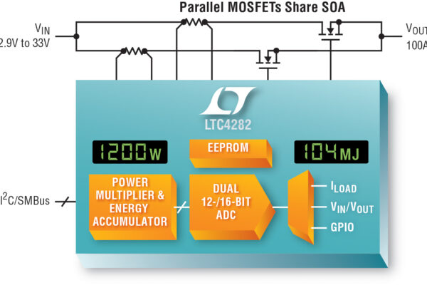
The LTC4282 is a hot swap controller and circuit breaker with energy telemetry and EEPROM (Figure 3), addressing high current applications with an innovative dual current path feature. The controller ensures safe turn-on and turn-off of supplies in the 2.9V to 33V range by controlling external N-channel MOSFETs to gently power up bulk capacitors, avoiding input supply glitches and damaging current levels. Sitting at the gateway to board power, the LTC4282’s 0.7% accurate 12- or 16-bit ADC reports board voltage, current, power, and energy consumption through an I2C/SMBus digital interface.

Internal EEPROM provides nonvolatile storage for register configuration and fault log data, speeding debug and failure analysis during development and field operation.
The LTC4282 has a 2% accurate current-limited electronic circuit breaker, minimizing overdesign which becomes more important at high power levels. During overcurrent conditions, the LTC4282 folds back its current limit to maintain constant MOSFET power dissipation for an adjustable timeout period. After the timer expires, the circuit breaker disconnects the faulting module from the common supply bus. An idle module can also be disconnected from the power bus, saving power. Digitally configurable circuit breaker threshold enables dynamic adjustment with load changes and eases selection of low value sense resistors. Minimum and maximum values of the monitored electrical parameters are recorded, with alerts raised when they exceed 8-bit adjustable thresholds. To prevent catastrophic damage to the board, the MOSFETs are continuously monitored for abnormal conditions such as low gate voltage and drain-to-source short-circuit or large voltage drop.
SOA Sharing Paths
Although the LTC4282 controls a single supply, it provides two parallel current-limited paths for the load current. High current boards with conventional single-path controllers employ multiple parallel MOSFETs to reduce on resistance, but all of these MOSFETs require large safe operating area (SOA) to ride through overcurrent faults since parallel MOSFETs cannot be assumed to share current during current limiting. Also, MOSFET selection narrows at higher current levels, prices go up, and SOA levels do not keep up with reduced RDS(ON). By splitting the current into two precisely-matched current-limited paths, the LTC4282 ensures that the two banks of MOSFETs share current even during an overload condition. For a 100A application, each path is designed with a 50A current limit, halving SOA requirements, widening MOSFET selection, and reducing their cost. This is called a matched or parallel configuration as both paths are designed with similar MOSFETs and sense resistors.
The LTC4282’s dual current paths are also used to decouple MOSFET SOA requirements from on-resistance. Large SOA is important for stressful conditions such as startup inrush, current limiting, and input voltage step. Low on-resistance reduces voltage drop and power loss during normal operation when the MOSFET gate is completely turned on. But these are competing requirements as MOSFET SOA typically worsens with improving on resistance. The LTC4282 allows using one path with a MOSFET capable of handling stressful conditions and the other path with MOSFETs having low on resistance. This is called a staged-start configuration. In general, the stress-handling path is turned on and the RDS(ON) path is kept off during start-up, current limiting, and input voltage steps. The RDS(ON) path is turned on during normal operation to bypass the stress path, providing a low on-resistance for the load current, reducing voltage drop and power loss. Depending on the amount of MOSFET stress at start-up, there are two types of staged start configurations—low stress (Figure 4) and high stress.

Provides Lowest Cost for > 50A Applications

GATE1 turns on first to trickle charge output with low 2A inrush current level.
GATE2 turns on when SOURCE (output) goes above powergood threshold.
The high stress staged start is recommended for application current levels below 50A, while the parallel and low stress staged start configurations are recommended for applications above 50A. As compared to a single-path design, lowest MOSFET cost is afforded by the low stress staged start configuration at the expense of limited transient ride-through and not being able to startup with a load current. The parallel and high-stress staged start configurations startup in to a load and afford longer fault timers, riding through longer lasting overload conditions and input voltage steps.
Conclusion
The adoption of electronic content in cars has rapidly increased in the last two decades, driven by functions such as power steering, ABS braking, convenience, safety, and entertainment. The pace is poised to accelerate further as cars head towards being completely connected and autonomous, raising demands on precious battery power. Careful power consumption monitoring along with shutting down idle systems promises to raise the efficiency of battery usage. By providing board-level electrical data, the LTC4282 circuit breaker eases the task of measuring the power and energy consumption of each sub-system and consequently that of the entire vehicle. With its novel dual current path feature, configurable in multiple ways, the LTC4282 greatly eases high current kilowatt level board designs, enabling both large SOA and low on-resistance in the same design.
About the author:
Pinkesh Sachdev is Product Marketing Engineer, Mixed Signal Products at Linear Technology
 If you enjoyed this article, you will like the following ones: don't miss them by subscribing to :