Efficient management of lead-acid batteries for Micro Hybrid Vehicles
In today‟s vehicles, the rising number of electrical loads presents a challenge to the battery. More than half of the vehicle breakdowns that are caused by the electrical system can be traced back to the lead-acid battery and could have been avoided by knowledge of the battery state. Additionally, new functions of micro hybrid vehicles like start-stop or intelligent alternator control require exact knowledge of the battery state.
A battery management system (BMS) provides the necessary information by fast and reliable detection of the State-of-Charge (SoC), State-of-Health (SoH) and State-of-Function (SoF) in terms of cranking capability. So, the BMS is able to minimize the number of vehicle breakdowns due to unforeseen battery failure, to maximize lifetime and efficiency of the battery and to enable CO2 saving functions. The key element of the BMS is an Intelligent Battery Sensor (IBS), which measures battery terminal voltage, -current and -temperature and calculates the battery state.
This paper describes the implementation of a BMS using state-of-the-art algorithms for calculation of SoC, SoH and SoF and the efficient implementation of these on Freescale‟s IBS for lead-acid batteries.
1) Introduction
Traditionally the charge level of a car battery has been an unknown factor, which in many cases resulted in vehicle breakdowns. Dependent on the vehicle life cycle, battery related failure rates could climb up to 10000 ppm [1].
Additional challenges to the already critical situation of the car battery are created by the increasing demand of electrical energy and power while CO2 emissions need to be reduced at the same time.
As electronics enable a large part of car innovation, increasing energy supply is required to account for growing functionality in comfort, electrification of safety relevant functions, hybridization of vehicles, driver assistance and infotainment.
On the other side more and more regulations call for reduced CO2 emissions and reduction of fuel consumption.
An advanced energy management system is required in order to manage those opposing requirements. It needs to guarantee that in a wide range of operating scenarios the battery is able to provide enough energy to crank the engine, and that the battery can be used as passive power source, for example to support intelligent alternators and start-stop systems.
2) Energy Management System
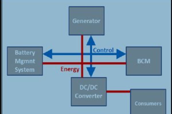
A typical power network as used to support start-stop systems consists of a Body Control Module (BCM), a Battery Management System (BMS), a Generator and a DC/DC converter (see Fig 1.)

Figure 1: Example power network as used in a typical start-stop system
The BMS provides the battery status to the BCM which, by means of specific load management algorithms, stabilizes and manages the power network by controlling the generator and DC/DC converter. The DC/DC converter distributes the power to the electrical consumers in the car.
The typical BMS of a lead-acid battery is directly mounted within a smart connector on a battery clamp. The connector consists of a low-ohmic Shunt resistor (typically in the 100uOhm range), a small PCB holding a highly integrated device with precision measurement and processing capability, called an Intelligent Battery Sensor (IBS, see Fig. 2). The IBS measures battery voltage, -current and -temperature with high resolution and accuracy even in worst case conditions and over lifetime to allow a proper prediction of State-of-Health (SoH), State-of-Charge (SoC) and State-of-Function (SoF) of the battery. These parameters are communicated periodically or on-request via an automotive certified in-vehicle network to the BCM.

Figure 2: A typical Intelligent Battery Sensor for lead-acid batteries
In addition to above functional and parametric capabilities, other key requirements for the IBS are low power consumption, to be able to operate in harsh automotive environments (i.e. EMC, ESD), conformance test of the in-vehicle communication interface (i.e. LIN) accepted by Car OEMs, Automotive grade test limits (six sigma limits on tested parameters), and of course to meet the AEC-Q100 qualification.
Freescale is announcing a fully integrated LIN Battery monitoring device based on Freescale S12 MCU Technology [2] that fulfills all the above mentioned parameters. The device contains three independent measurement channels for current measurement via external shunt resistor, battery voltage measurement via series resistor directly at the battery plus pole and temperature measurement with integrated sensor. An integrated LIN 2.1 interface is used to directly connect the sensor to the LIN Bus without further components. Freescale‟s IBS is fully automotive qualified according to AEC-Q100.
In the following chapters, the implementation of a BMS using Freescale‟s IBS is described as well as how high efficiency of the BMS can be achieved by using the IBS‟ hardware features and fix point math.
3) Battery monitoring
As mentioned in 2), the main purpose of the IBS is to monitor the state of the battery and to communicate the state variables to the BCM or other ECUs if required. As inputs for the battery monitoring, the measured battery current, battery voltage and temperature sample values are used. The outputs of the battery monitoring are SoC, SoH and SoF.
3.1) State-of-Charge (SoC)
The definition of the SoC is rather intuitive and usually expressed in percent. A fully charged battery has a SoC of 100%, a fully discharged battery has an SoC of 0%. The SoC changes with charging and discharging the battery.
This leads to formula (1), where Cr is the remaining (dischargeable) capacity of the battery and Ca is the total available battery capacity:

However, there is the problem that the available battery capacity is often different to the nominal capacity (which is usually labeled on the battery housing). For a new battery, it can be even higher than the nominal capacity, and over lifetime of the battery, the available capacity decreases. An additional problem is that the actual available capacity is very difficult to determine based on the input values of the IBS.
So, the SoC is often rated to the nominal capacity Cn, which has several advantages:
- Available amount of charge in the battery at a specific SoC is known, including for aged batteries
- Defined current (I=Cn/20h) and temperature (27 °C) at which Cn was tested
For SoC calculation, there are 2 popular methods: Coulomb counting, which is also known as current integration or Ampere-hour balancing, and the Open-Circuit Voltage (OCV) measurement.
The coulomb counting method is the best method to track fast changes of the SoC. It is based on integrating the current that is flowing in and out of the battery and adapting the calculated SoC of the battery accordingly. The formula (2) is used for the SoC calculation, where Q(t0) is the initial charge of the battery, α is the efficiency factor, i(t) is the current (positive or negative) and Cn is the nominal capacity of the battery.

The parameters in the formula are quite intuitive apart from the factor α. This factor describes an effect which is known as Peukert‟s law [3] [4]. It expresses the capacity of a lead-acid battery in terms of the rate at which it is discharged. As the discharge rate increases, the battery’s available capacity decreases. Another parameter which impacts the available capacity is the temperature. At higher temperatures, the available capacity is higher. Both effects are described using α, so there is a 2-dimensional array (temperature vs. discharge rate) of α-values required. According to measured temperature and discharge rate, the appropriate value is taken for each integration step individually. The α-values are highly dependent on the battery design and chemistry and are usually different even for varying models of a manufacturer. They are usually obtained from charge- and discharge tests in the lab.
Although Peukert‟s law is only valid for discharging, an efficiency factor similar to α has to be applied for charging cycles too. In addition to temperature and charge rate, the actual SoC has to be taken into account, because the charge efficiency at high SoCs is smaller than at moderate SoCs.
Due to the integration of the current and alpha values, the error that results from the changing battery conditions and current measurement- and quantization errors gets larger over time. So, the parameter Q(t0), which is the starting point of the current integration, is usually obtained by a different method that provides better accuracy: the OCV method. The OCV is the voltage between the battery poles if no consumers are drawing current from the battery.
Lead-acid batteries show a good linear relationship between OCV and SoC. So, by measuring the OCV, the SoC can be calculated directly. The exact factor between OCV and SoC has to be characterized.
The only drawback of this method is that the OCV can only be measured if the car is parked, i.e. (nearly) all consumers are off, as well as after a period of several tens of minutes to even hours after the car has been turned off.
As a result, the OCV method is used to recalibrate the coulomb counting as often as possible and the coulomb counting method runs continuously. This combination provides a good calculation of SoC and can be further refined by correcting the SoC with the self-discharge rate during long parking periods.
3.2) State-of-Health (SoH)
There are various aging effects for lead acid batteries that have different impacts on the battery [5]. As they are difficult to detect and quantify individually with an IBS, the SoH is usually not directly rated with respect to these aging effects. Instead, it is rated towards reduction of capacity over lifetime, which is the major result of the aging. A second very important parameter, which is connected to the battery aging, is cranking performance; but this is usually expressed with the State-of-Function (SoF) for cranking capability (see section 3.3).
So, the SoH is estimated with formula (3), where Caged is the aged capacity and Cn is the nominal capacity taken as reference as per the SoC calculation.

As Cn is known, the critical task to calculate the SoH is to find out Caged . A possible way is to track the maximum reached charge (or SoC) over lifetime. If the maximum charge level of the battery is below the previously calculated aged capacity after several subsequent full-charges, the aged capacity has become smaller. Accordingly, Caged and the SoH have to be adapted with the capacity determined by coulomb counting and OCV method. The fully charged state can be detected as the decreasing of the charging current below a certain threshold.
Another method to determine the SoH is to track the charge and discharge cycles and rate them to the cycle stability given by the battery manufacturer. Usually, there is an amount of charge/discharge cycles of a given depth at a given temperature guaranteed by the manufacturer, e.g. 500 cycles with 25% depth-of-discharge at 27 degrees Celsius. By rating all the cycles towards these numbers and applying correction factors for the temperature and the state-of-charge, the tracking of Caged as mentioned above can be supported. These correction factors have to be found out by characterization of the battery.
However, these two methods are usually combined with other proprietary algorithms which are tightly coupled to observation of several battery parameters over lifetime. These battery parameters are found out from extensive battery characterization in the lab and usually work just for a specific battery model.
3.3) State-of-Function (SoF)
A very important function, if not the most important function, of the lead-acid battery is to crank the vehicle‟s engine. So, a very important task of the BMS is to predict whether cranking is possible or not under the actual conditions. This cranking prediction is expressed with the SoF parameter.
Besides the “traditional” cranking after parking, the cranking prediction becomes even more important through the introduction of start-stop systems in Micro-Hybrid vehicles. The BMS has to decide and communicate to the BCM if it is possible to crank the engine again after stopping it and if it is safe to enter stop mode, or not, accordingly.
A good way of obtaining the SoF is to analyze the most recent engine cranks, the remaining battery charge (as a function of SoC and SoH) and the actual temperature. During cranking the internal resistance (Ri) of the battery (which is calculated from voltage drop and current) needs to be recorded. As Ri is usually quite constant over lifetime and rises significantly just before end of life of the battery [5], the average value of Ri needs to be below a certain threshold to guarantee safe cranking. Another effect of aged batteries is that during the cranking phase, the calculated Ri values from the voltage and current samples tend to be non-linear [5], i.e. there are different current values for equal voltage samples. For new batteries, Ri is linear. See Figures 3 and 4 for typical voltage and current profiles during cranking.

Figure 3: Cranking voltage profile

Figure 4: Cranking current profile
Ri (as calculated from voltage drop and current) together with the remaining amount of charge in the battery and the actual temperature give a good indication of cranking capability. Again, the thresholds have to be determined with battery characterization.
In order to determine linear or non-linear behavior of Ri with the necessary accuracy, all the voltage and current values that are sampled during the cranking phase need to be filtered with a linear filter, preferably a band-pass.
4) Efficient implementation of the BMS in hardware and software
Electrical energy efficiency is one of the most important characteristics of new vehicles, which is enabled by the BMS. Besides managing some energy saving functions, the BMS needs to be energy efficient as well because it is one of the systems that is always active and supplied by the lead-acid battery when the alternator is not active. In order to fulfill this requirement, power consumption of the IBS needs to be as low as possible.
To achieve this, Freescale‟s IBS implements two low power modes in which the CPU and other not needed hardware (HW) blocks are turned off. To reduce power consumption in normal mode, and also to reduce software (SW) development effort at the customer, additional HW blocks are added in order to decrease SW complexity. By doing this, it is possible to use a smaller, lower power- and more cost efficient 16-bit microcontroller. Another measure implemented to decrease SW complexity is to guarantee product parameters over lifetime and to store factory trimmed calibration values in the non-volatile memory (NVM). As part of the end-of-line testing, these calibration values are characterized for each chip individually and stored appropriately. So, no complicated calibration algorithms are necessary in SW.
As well as these three techniques implemented in HW, this chapter provides information on efficient SW implementation of the battery monitoring algorithms (see chapter 3).
4.1) Low power modes
The implementation of low-power modes is a very good measure to reduce power consumption. This is achieved by switching off parts of the SoC (especially the CPU) when they are not needed, and changing to normal mode (i.e. activate all HW blocks)
only when required. As noted earlier, there are 2 low-power modes, which differ only in the program entry point that is used by the CPU after wake-up.
However, it is necessary that the battery state is observed also during low-power mode, i.e. without SW interaction. Primarily, it is necessary to keep track of the current for the coulomb counting method for SoC calculation. Accordingly, current measurement during low power mode, and automated summation of the current sample values (i.e. coulomb counting) during the low power mode, are supported.
The IBS must be able to react to state changes of the battery and the vehicle, i.e. the battery sensor must wake-up on various events. Accordingly, current and temperature need to be measured during low power mode. Whilst changing current usually indicates a change in the vehicle‟s state (consumers have been turned on or off), changing temperature sometimes requires recalibration of the measurement channel parameters (also see 4.3). Thresholds for current and temperature sample values can be configured and if these are exceeded, a wake-up is initiated. A wake-up on a threshold of the automated coulomb counter can be used too.
Beside those wake-up events on measured parameters, there are wake-ups implemented which allow the BCM or other electronic devices in the vehicle to wake-up the IBS (with a LIN message or a direct wire connection), and there are timed wake-ups.
The implementation of the low-power modes and wake-ups as described allows the IBS to run in low-power mode most of the time (usually about 70%), including when the engine is running. During normal operation, the SoC, SoH and SoF parameters are recalculated.
4.2) Moving SW tasks to HW blocks
The implementation of dedicated HW blocks to remove tasks from SW is an efficient way of reducing SW complexity and saving power. Such HW blocks are very efficient for preprocessing of the voltage, current and temperature measurement samples before using them in the battery monitoring algorithms. This is necessary because there is usually noise on the power line in the vehicle and the requirements on the measurement accuracy of the sampling values are very high for the IBS.
High precision 16-bit sigma-delta ADCs followed by decimation and noise-cancellation filters are very well suited for the application because of their high measurement accuracy compared to other ADC technologies. Together with error compensation (see 4.3), this already provides very good accuracy. However, it is often desired to filter the samples again after the signal processing chain. One reason can be to remove noise from other electric devices in the vehicle whereby freely interchangeable frequency characteristics of the filter are required. Another reason is that specific battery parameters which are observed as part of the battery monitoring are tightly coupled towards excitation frequencies that are specific to the battery chemistry. This is the case, for example, for Ri.
A programmable linear filter fulfills these requirements: the filter coefficients can be passed via registers to the HW filter block. These registers are programmed once, and then there need not be any more filtering done in SW.
A challenge in the current measurement results from the fact that there need to be high measurement accuracy for small currents while a large measurement range must be supported. The required accuracy is better than 10mA, which translates into a voltage drop of 1μV across the 100 μOhm shunt; whereas during vehicle cranking, currents of 1000A and above are seen. To support both requirements while avoiding manual
measurement reconfiguration from SW, an automatic gain amplifier needs to be implemented. A selectable gain factor adjusts the input signal to optimally fit into the reference voltages of the ADC. This gain factor adjustment can be done automatically and there is no SW reconfiguration necessary during runtime. For testing purpose or if there is a special application requirement, fixed gain factors can be chosen too.
4.3) Eased calibration
A very important task to guarantee device accuracy over lifetime is trimming and calibration. For that purpose, previously tested correction factors are applied to critical device parameters. These factors are tested for various temperatures as part of the device testing on the production line and are stored in the NVM of the IBS. At device startup, the respective trimming parameters have to be written to device registers by SW. Parameters that need to be trimmed are found in the current- and voltage measurement chain, and also the oscillators, voltage references, and the LIN timing need to be trimmed. During runtime, re-calibration needs to be done, for example periodically or if the temperature changes drastically. If appropriate, different correction factors have to be written to the respective registers again.
The calibration feature described avoids costly end-of-line testing for these parameters at the customer. Additionally, through the simple application of parameters, there is low SW complexity for calibration.
4.4) SW implementation
The battery management algorithms that are mentioned in chapter 3) require processor intensive calculations and control algorithms. Usually, the first implementation of these algorithms is done using a model-based simulation tool on the PC. These tools normally use floating point data formats. Later in the development process, the algorithms are ported onto the IBS. However, for cost and power consumption reasons, there is no floating point hardware available on the class of microcontrollers used for IBS. So, the data types that are used in the algorithms have to be mapped to fix point integer format in order to achieve applicable run-time. There are several data types and inherent value ranges available. As example, the data types which are available on Freescale‟s IBS are presented:

To represent values that are smaller than 1, the LSB is mapped towards a certain value. This value is determined by the required resolution. By choosing one of the available data types, this leads to an available value range for the variable and to a virtual fixed decimal point („fix point format‟). For example, a resolution of 1mV and the data type unsigned integer results in a range of 0 to 65.535 Volts.
Due to the fact that there is a 16-bit S12 CPU in Freescale‟s IBS, the integer data type offers 16 bit precision. This means that 8- and 16-bit variables are processed with higher performance than 32-bit values. Accordingly, it is preferable to use 8- and 16-bit variables as often as possible.
Exemplary implementations of the above mentioned algorithms for SoC, SoH and SoF calculation show that in many cases, 16-bit variables provide sufficient value precision and range. This is enabled by the fact that voltage and temperature input values have 16-bit precision (through the use of 16-bit ADCs). Other values where 16-bit width is sufficient are for example SoC, SoH, Ri and the correction factor α (see chapter 3 for a description). Even the current sample value, which is 24-bit, can be mapped to 16 bit most of the time. At a precision of e.g. 3mA and by using signed 16-bit integer format, currents of up to +/- 98.3 A can be represented without further modifications to the number format. This is sufficient during driving and parking of the vehicle. During cranking, the current sample values exceed this border, and 32-bit data format has to be used. Parameters where 32-bit format is necessary are the battery charge related values (e.g. coulomb counter).
5) Conclusion
This paper shows the efficient realization of BMS for Micro Hybrid Vehicles using Freescale‟s IBS. State-of-the-art algorithms for battery state calculation (SoC, SoH and SoF) are presented. It is shown how special hardware features are used to improve the efficiency of the IBS in terms of power consumption. The use of low-power modes with automated battery state observation (no SW interaction necessary) and sophisticated wake-up mechanisms is presented. As a result, the IBS is able to stay in low power mode for the majority of time. Additionally, through proper HW signal processing, programmable filtering and eased calibration, it is shown that SW complexity is reduced. The principle of fix point math is presented and it is indicated that 16-bit fix point data format is often sufficient for the variables in the BMS algorithms and 32-bit is only sometimes required.
References
[1] Allgemeiner Deutscher Automobil-Club e.V., Aggregate supplier indicative data for 2004-5 Europe and North America
[2] Datasheet Freescale intelligent Precision Battery Sensor, MM912J637
[3] W. Peukert, Über die Abhängigkeit der Kapazität von der Entladestromstärke bei Bleiakkumulatoren, Elektrotechnische Zeitschrift 20 (1897)
[4] D. Doerffel, S.A. Sharkh, A critical review of using the Peukert equation for determining the remaining capacity of lead-acid and lithium-ion batteries, Journal of Power Sources, 155 (2006) 395–400
[5] Grube, Ryan J., Automotive Battery State-of-Health Monitoring Methods, Master Thesis, Wright State University, 2008.
About the authors:
Michael Hutterer is Systems Engineer for Battery Management Products within Freescale’s System Solutions Engineering.
Since 2009 Michael is working on Battery Management and is active in the fields of Application Engineering, IC Definition and Customer Support for Freescale’s Battery Management Products. With more than 6 years experience in the semiconductor industry Michael has held various positions in Engineering.
Michael holds a Masters degree in Hardware/Software Systems Engineering from the University of Applied Sciences in Hagenberg, Austria.
Antonio Leone is Product Line Manager for Battery Management System Products within Freescale’s Analog Mixed Signal Power Division.
Since June 2005 Antonio has been responsible for Product Marketing for MCU+Power Products and since August 2008 Antonio joined his actual position. With more than 20 years experience in the semiconductor industry Antonio has held various senior positions in Engineering, Marketing and Product Management.
Prior to his current role, Antonio held different senior engineering positions in product development for Microcontrollers and Mixed-signal Analog products within Motorola and Freescale Semiconductor.
Antonio holds a Physics Engineering degree from Munich University of Applied Sciences and an MBA in from Augsburg University.
 If you enjoyed this article, you will like the following ones: don't miss them by subscribing to :