
To reduce vehicle power consumption and increase efficiency, start at the charging system
One of today’s major challenges for carmakers is improving the fuel efficiency to reduce the vehicle’s fuel consumption and its carbon footprint. Among the reasons for placing a high priority on improved fuel consumption are (1) taking advantage of tax incentives offered by regional governments for low emission vehicles and/or (2) avoiding increased taxes and fines for inefficiency and high fuel consumption vehicles. To meet the goals being established by governments in many regions of the world, all the stops must be pulled out. As a result, every vehicle system is expected to contribute towards improved efficiency. A recently released alternator regulator integrated circuit (IC) provides improved control allowing the charging system to do its part towards achieving greater efficiency. With its Local Interconnect Network (LIN) 1.3 interface, the IC enables simplified, standardized and robust communications with the engine control unit (ECU).
The alternator provides the source of power for vehicle loads and charging the vehicle’s battery. With diode rectification, a typical belt-driven claw-pole automotive alternator has limited efficiencies. Improved slot fill techniques for the stator windings can improve some production alternators from +15% up to +20% efficiency ranges. In addition, the synchronous rectifier, brushless dc machines used in starter-alternators in stop-go systems can add efficiencies of +10%, according to automotive market. Both of these improvements come at increased cost and are not typical of the vast majority of automotive alternators. Still, improving the charging system’s efficiency is a highly desirable goal.
From a systems perspective, one means of improving the efficiency and reducing the energy consumption involves improved control. Typically, a conventional analog voltage regulator simply increases or decreases the amount of rotor current and provides a voltage to an indicator lamp if there is a problem as well as a signal to a microcontroller (MCU). Using the low-cost LIN protocol, the alternator regulator can be interfaced to an ECU that manages the charging system to improve operation under a variety of conditions. Figure 1 shows how the alternator, regulator, battery and control connect in an interfaced charging system.

Figure 1. The interfaced charging system uses the LIN protocol to communicate control and diagnostic information to the ECU.
The LIN–Controlled Alternator Voltage Regulator System on Die
Freescale’s SMARTMOS™ mixed-signal processing technology that combines analog, digital and power circuitry can provide the comprehensive intelligent regulation requirements in a signal IC. The TC80310 is a LIN-Controlled Alternator Regulator IC that provides the interface as well as several integrated functions for highly programmable regulation of the supplied power. Driven by customers’ request for standardized components, the IC is an application-specific standard product (ASSP) designed specifically for alternator control.
While the TC80310 is the latest Freescale ASSP to use the LIN interface to regulate the power provided to the alternator, it is not the first IC for this purpose. It is actually an upgraded version of a previous design that has been used in production vehicles for over five years. Prior to its release as a standard product, the latest version was designed to provide improved functionality as well as increase process quality to target a zero-defects strategy.
As shown in Figure 2, the IC has a digital core, one-time programmable (OTP) memory, and a phase processor, as well as a 10-bit analog to digital converter (ADC) and several analog IC blocks. From the power technology capability of SMARTMOS technology, the IC integrates a high-side excitation driver for the rotor field and an internal free-wheeling diode to circulate the energy when the rotor coil current is turned off to avoid excessive voltage. Only seven circuit connections and no external components are required to provide the complete voltage regulator.

Figure 2. The TC80310 block diagram shows the key elements of the IC and external connection.
For optimum control response, the ASSP circuitry must be placed very close to the alternator. This requirement, as well as the preferences of many alternator manufacturers, results in the TC80310 being offered only in die form. Also, other reasons, such as space restrictions in the alternator and the need to avoid excessive stress from high operating temperature that would occur to an encapsulated plastic package, dictate die packaging. Figure 3 shows the die layout with the bond pad locations identified.

Figure 3. Overview of the TC80310 : shows die bond connections and function required for full system functionality.
The “system on die” ASSP provides everything required for the charging system, it just needs the alternator. Protection and harsh automotive environment capability are built into the IC. Electrostatic discharge (ESD) performance provides a good example of these capabilities. When tested according to the human body model, all pins can typically withstand ±6 kV (Except Phase input at ±5KV) and for the machine model it is ±200V. When mounted on the alternator, the accessible Bus and B+A pins can withstand ±8 kV according to the IEC61000-4-2 specification.
In addition to surviving load dump values up to 40V (per ISO7637-2), the IC can withstand standard transient pulses per ISO7637-1 & -3 up to 150V. The integrated alternator regulator chip has an junction temperature (Tj) range of -40°C to 150°C and thermal shut down at 185°C (with 10°C hysteresis).
Since the LIN alternator regulator is available in die form only, the wire bond requirements are well within the industries’ capabilities, especially for those companies that have previously used semiconductors in die form. Users only have to attach seven of the same size wires to obtain full system regulator performance of the automotive-qualified IC.
Improved Control
The LIN 1.3 interface of the TC80310 enables simple, low-cost bi-directional communication between the ASSP and ECU for real-time control and optimized charging system performance. Information provided by the ASSP includes programmed regulated voltage, alternator excitation current, die temperature and more as well as mode status and diagnostic data. Through software, the ECU has the ability to modify the system’s operation. For example, U.S. Environmental Protection Agency’s Corporate Average Fuel Economy (CAFE) and Europe’s Euro 6 emission limits can be addressed by controlling the alternator to optimize energy consumption according to different operating profiles for torque management.
Referring to Figure 2, the OTP block allows an easy configuration and adjustment of the circuit. The non-volatile memory (NVM) bits are programmed during the IC’s factory test phase. Twenty user-selectable parameters allow optimization to specific user requirements. The amount of memory and programming makes the 80310 extremely flexible.
The charging system achieves faster response time once load response control (LRC) disable frequency is achieved. LRC eliminates engine speed hunting and vibration due to sudden electrical loads that cause abrupt torque loading of the engine at low RPM. This digital control of the regulator function has OTP selectable variables including: LRC Disable RPM Default (fLRC) that can be set at 2400, 3000, 4000 RPM or never; and the LRC Rate that can be set at 0, 3.0, 6.4 or 12.3 seconds.
The IC has a state machine with Standby, Wake-up on Phase, Wake-up on LIN, PRE-EXC, EXC 100% DC, Regulation with LRC, Regulation w/o LRC and Phase regulation modes. These different modes have specific responses from the ASSP and in many cases, the LIN connection enables enhanced control from the ECU including input involving transitions between states. Additional adjustments for Loop Regulation include ramp and digital filter capability. The regulation frequency is at 122Hz Typ.
The T° Measurement block in Figure 2 generates a voltage proportional to the die temperature. The ADC converts the voltage into a digital value that is transmitted via the LIN bus to the controller. This temperature is also used in the thermal compensation (TC) concept.
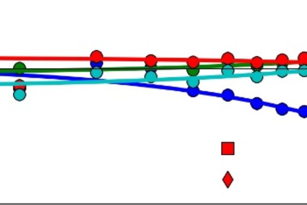
On the ASSP, TC reduces the regulation voltage when the temperature increases. This compensation is activated when the temperature in the circuit reaches a threshold defined by the NVM (from 135°C to 160°C). How fast this occurs is determined by one of four main slew rates defined for this function of -50, -100, -200 and -400 mV/°C. Four selectable temperature threshold points to activate the TC are 135, 145, 150 or 160°C. In addition, four main regulation voltage groups have been defined. Figure 4 shows how the IC responds to the different slew rates and voltage regulation set points over temperature. Once the temperature in the circuit reaches the thermal shut down point at 185°C, the regulation is off. The reduced voltage regulation at higher temperatures avoids thermal runaway.

Figure 4. Thermal compensation programmability provides a considerable degree of flexibility to the alternator manufacturer.
The design includes a selectable default regulation voltage from 10.6V up to 16V that is programmable by Freescale during final test. This value is important because it is the value that the alternator manufacturer uses to control the regulation to optimize alternator performance as well as battery life during the lifetime of the vehicle.
In addition to the selectable regulation voltage, the die has additional overvoltage and undervoltage operating modes. The initial overvoltage range of 16 to 21V provides excitation with minimum PWM duty-cycle. Above 21V, or the load dump detection range, the excitation is “off”.
In the first lower voltage range (from 10.6 to 8.5V), excitation is available with 100% of duty-cycle based on a targeted value in logic RAM. Next, from 8.5 to 5.0V, the previous logic configuration is maintained. Its value is based on the last targeted value stored in logic RAM. This results in 100% duty-cycle without any LRC function. Finally, values below 5V result in a logic reset based on a default regulation target.
One of the main operating features of the IC is the ability to control an excitation coil current up to 8.0A. This covers the full range of alternator requirements for alternators rated at up to 150A and even more than 200A. At the other end of the power spectrum, the unit’s low power mode and wake up strategy address the need for conserving power. With power applied to the alternator phases, the maximum current draw (at 25°C) is 250 µA in the sleep mode.
With the alternator phases at 0V, the maximum quiescent current is 110 µA (at 25°C). This low level reduces the drain on the battery, especially when the vehicle is parked for an extended period of time.
Fault detection includes Mechanical Fault, Electrical Fault, Thermal Fault, LIN Bus time-out, Comm error and LIN protocol errors. The extensive diagnostics that the IC provides shows how far a digital-controlled alternator has progressed beyond the simple idiot light of analog control.
While the TC80310 has enhanced functionality from its LIN connection to an MCU, it can operate in a standalone, self-start mode in case of LIN disconnection.
Development Ecosystem
With twenty OTP programmable functions to manipulate to optimize systems design, the alternator designer’s task is a little more complicated than with a simple analog regulator. To simplify evaluation of the die and reduce design cycle time, an evaluation board (EVB) with easy to use software is available. As shown in Figure 5, the alternator with the TC80310 connects to the LIN EVB and the EVB connects to a PC. For evaluation purposes, the die form of the IC is available in a TO-3 package to simplify the mounting. A graphical user interface (GUI) allows the user to access all the programmable aspects of the IC. The software for the EVB is downloaded from Freescale’s website.
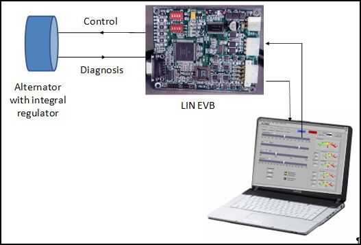
Figure 5. The EVB provides full control of the regulator through the LIN interface.
The ecosystem helps debug the product inside the application. With such EVB, Freescale offers an easy to use solution to mount the IC in a test unit, conduct an evaluation and select specific programmable parameters within a month.
Improved Control & Efficiency
Through improved control for the regulation loop, Freescale TC80310 helps contribute to the overall car energy efficiency savings goal of 20% that many carmakers have established, with direct contribution at the power generation area of the car. Alternator suppliers and carmakers can optimize the charging system based on the selection of programmable parameters. But also by managing the application modes and optimizing the power generation performance under different vehicle conditions, the ASSP helps reducing CO2 emissions and contributes towards meeting harsh legislated regulation requirements as well.
 If you enjoyed this article, you will like the following ones: don't miss them by subscribing to :