
Testing the MOST150 Coax Physical Layer
A sophisticated concept for Physical Layer Testing on ECU level was already created for the MOST150 optical Physical Layer. The test usually establishes a running network and enables access to the transmitter output, thereby verifying the majority of parameters, which were defined at the specification point of the transmitter output, SP2. In addition, a consistency test of received bit information is performed while the receiver input is provided by a stress test pattern via different transmission channels representing the limits of the MOST Physical Layer Specification.
During the last few years, this test concept was successfully used to perform MOST150 limited optical Physical Layer Tests , and therefore, it is a feasible starting point for developing a test setup that covers the demands for the MOST150 cPHY Technology.
Requirements for MOST150 Test Setups
Figure 1 shows the different test setups for simplex and duplex cPHY testing and the oPHY test setup for comparison. A MOST Tester device (Physical Layer Stress Test Tool – PhLSTT) is used to build up an operating ring network, acts as a stress test generator, checks for data consistency, and reads stored failures from the ECU memory of the device under test (DUT). In the test setup for MOST150 limited oPHY, which is described in MOST150 oPHY Compliance Verification Procedure [1], the PhLSTT is able to generate additional stress for the DUT by changing the duty cycle of the MOST150 pattern. Different optical transmission channels are simulated by using a 2m fiber for a high bandwidth channel and a 15m fiber in combination with a mode scrambler for a low bandwidth channel. An integrated optical attenuator enables different input power levels. An optical splitter in the TX path of the DUT provides access to the SP2 interface and also a return path to the PhLSTT.

For higher resolution click here
The test setup for MOST150 limited cPHY, described in MOST150 cPHY Compliance Verification Procedure [2], utilizes some of the functions of the PhLSTT but requires some additional features that have to be realized by an external extension to the PhLSTT. This extension is called MTCM and is described in MOST150 Tester Cable Model [3].
MTCM for cPHY – Extension Tool for Physical Layer Stress Test Tool
The main purpose of the MTCM is to emulate a transfer function, which represents a coax interconnect on a MOST150 stress pattern. The MOST150 pattern is created by the PhLSTT and feeds the DUT. Three different cable models are defined in order to simulate a transmission channel, which covers typical use cases in the car. A transmitter with adjustable rise and fall times drives these cable models, which represent a short, mid and long transmission line. An integrated coupler splits the incoming signal from the DUT into a path for oscilloscope measurements and a return path to the PhLSTT. One of the advantages of the cPHY technology, in terms of measuring MOST signals, is the fact that the transmission system is terminated by 50 Ohms and therefore can be directly attached to an oscilloscope without an additional probe. The MCTM is able to provide a test solution for simplex as well as for duplex operations. For duplex operations, an additional noise adder option is available when an external signal source is connected to the MTCM.
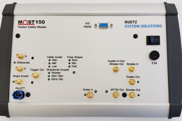
Inside the MTCM
The block diagram of the MTCM is shown in Figure 2. The MTCM is designed to work with various input signals, either single-ended or differential signals, as provided by SMA or HSD connectors. (HSD allow direct connection to the PhLSTT.) Element Switch Input Selection in the block diagram selects a dedicated input and routes the signal to the required cable model channel. Each cable model channel consists of a Signal Shaper element and the Cable Model itself. The signal shaper is based on a 50 Ohm transmitter that can be adjusted for different predefined rise and fall times from 700ps, 1000ps and 1400ps. The shaper also allows setting the steady-state amplitude in a range from 300mV up to 420mV. Each of the three different cable models is attached to a separate signal shaper to provide seamless integration.

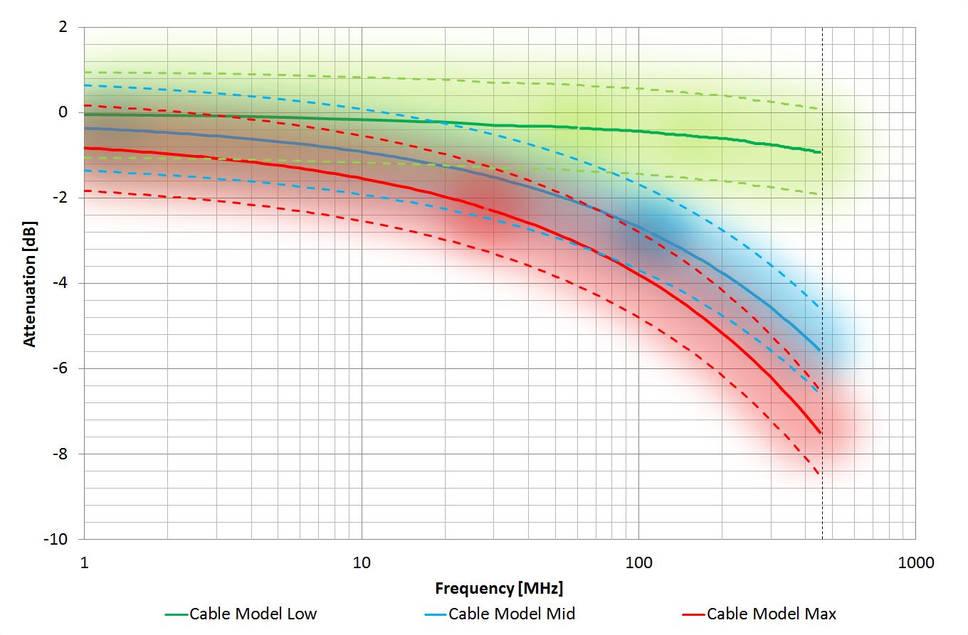
Design requirements for each cable model are shown in Table 1. Cable Model “Low” describes a short test cable with fast rise and fall times and maximum steady-state amplitude. Cable Model “Mid” is intended to cover a typical cable connection and cable model “High” is built to simulate the worst-case channel with slow rise and fall times of 1400ps and minimum steady-state amplitude of 300mV. Figure 3 displays a comparison of the three implemented cables models.

The outgoing signal of the particular cable models is routed to the output connection of the MTCM (In-Out Duplex, Out Simplex) via a Directional Coupler element. In a duplex operation, signals are distributed over one single cable in both directions. Therefore, the directional coupler is used to split the incoming from the outgoing signal. The incoming signal is forwarded to a Measurement Amplifier which generates an output signal for analysis by an oscilloscope and, simultaneously, providing the needed return signal for the PhLSTT to close the ring network for data consistency testing. The gain of the Measurement Amplifier can be turned to low or high amplification to compensate the loss of the internal directional coupler.
For the simplex setup, the directional coupler is still part of the outgoing channel to maintain identical channel characteristics for both simplex and duplex. However, the return path is established by an additional input connector (IN Simplex) and uses the measurement amplifier to create signals for oscilloscope and PhLSTT. For duplex, an additional Noise Adder element is implemented to simulate the worst case noise that can be created by the return loss of coax interconnect and tested device. The noise adder can be supplied by an external signal generator connected to Input Noise In. An additional trigger output and a bypass function for the directional coupler enables start up and shutdown testing.
Automation of MOST150 cPHY Test Setup
The internal microcontroller regulates all functions of the MOST Tester Cable, which can be accessed by a serial interface. A documented application-programming interface is provided. A fully automated solution, which controls the complete MOST150 limited cPHY test setup, will be available, consisting of the Physical Layer Stress Test Tool (PhLSTT), the MOST Tester Cable Model (MTCM), a power supply and an optional temperature chamber.
The MOST Tester Cable Model provides a highly integrated solution to implement an MOST150 limited cPHY Test Setup. All requirements specified in the MOST150 cPHY Compliance Verification Procedure [2] can be met. MTCM allows easy migration to a MOST150 limited cPHY test setup for those already using an existing MOST150 limited oPHY test setup with a Physical Layer Stress Test Tool.
References:
- MOST150 oPHY Compliance Verification Procedure Revision 1.1-00 from 07/2010
- MOST150 cPHY Compliance Verification Procedure Revision 1.0-00 from 11/2015
- MOST150 Tester Cable Model Revision 1.0 from 07/2015
About the Authors:
Dipl.-Ing. (FH) Jörg Angstenberger is Head of Test Laboratory and Technology Assessment of RUETZ SYSTEM SOLUTIONS. He has been assessing and improving the functionality and reliability of devices in the area of automotive electronics for more than 15 years.
Dipl.-Ing. (TU) Frederic Garraud is a Test Engineer at RUETZ SYSTEM SOLUTIONS. He is responsible for advanced development of MOST Network System.
 If you enjoyed this article, you will like the following ones: don't miss them by subscribing to :